RC Beam Deflection Checks to TS500
Summary
Expanded Content
RC Beam Deflection Design for Rectangular and Flanged Sections
Reinforced concrete (RC) beams play an essential role in supporting and distributing loads within structures. Designing these beams involves a careful balance between strength and serviceability. Deflection, or the bending displacement of a beam under load, is a critical parameter to ensure user comfort, structural integrity, and compliance with building codes.
This guide focuses on deflection design for rectangular and flanged RC beam sections, emphasizing calculations based on TS500 regulations. Proper deflection design helps prevent issues like cracking, vibration, or structural failure while maintaining the functionality and aesthetic quality of the building.
Immediate and Long-Term Deflection in RC Beam Design
Deflection is divided into two main categories: immediate and long-term.
- Immediate Deflection: This occurs when loads are first applied to the structure. It depends on factors like the material’s modulus of elasticity, the moment of inertia of the section, and the type and distribution of loads.
- Long-Term Deflection: Over time, creep and shrinkage in concrete, as well as sustained loads, contribute to additional deflection. Long-term behavior must be accounted for in RC beam design to ensure the structure remains serviceable throughout its life.
Step-by-Step Guide to RC Beam Deflection Design
- Determine Cross-Sectional Properties: For rectangular and flanged sections, calculate the area of concrete, reinforcement ratios, and moment of inertia.
- Calculate Immediate Deflection: Use standard formulas to compute deflection under applied loads, incorporating the effective span, material properties, and load distribution.
- Account for Long-Term Effects: Apply modification factors to include creep and shrinkage effects based on TS500 guidelines.
- Verify Against Code Limits: Compare calculated deflection with permissible limits set by TS500 to ensure compliance.
Numerical Examples of RC Beam Deflection Design
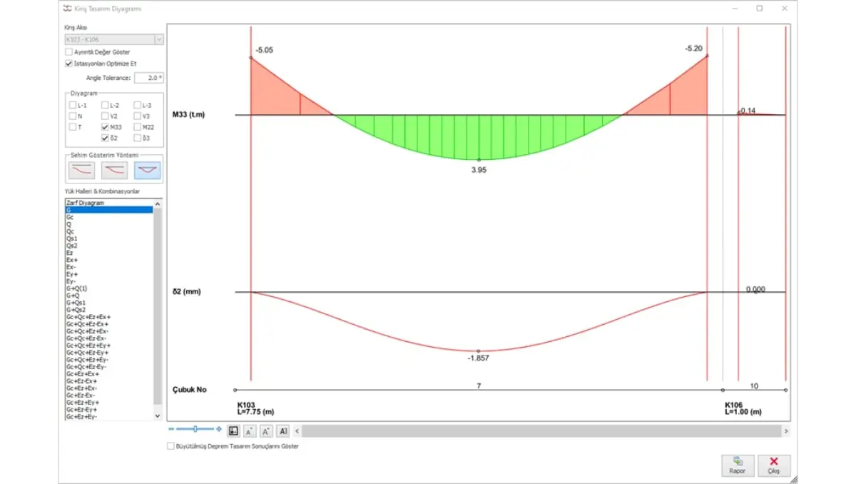
A typical example involves designing a T-beam subjected to uniform loading. By calculating the moment of inertia for the flanged section and applying creep coefficients, the total deflection can be determined step by step. Numerical examples like this illustrate how engineers can adapt theoretical concepts to real-world situations.
Real-World Applications
Understanding deflection behavior isn’t just theoretical—it directly impacts real-world construction projects. Visit ProtaStructure’s Project Gallery to explore examples of buildings, bridges, and other structures where accurate RC beam deflection design played a crucial role.
To learn how engineers worldwide solve complex challenges using advanced tools, browse Customer Success Stories. These case studies demonstrate innovative applications of deflection design principles and highlight how ProtaStructure supports engineers in achieving precision and efficiency.
Why Proper Deflection Design Matters
Ignoring deflection considerations can lead to issues like excessive cracking, sagging floors, or even structural failure. By adhering to TS500 guidelines and incorporating accurate deflection calculations into your designs, you ensure your projects meet the highest standards of safety, durability, and user comfort.


