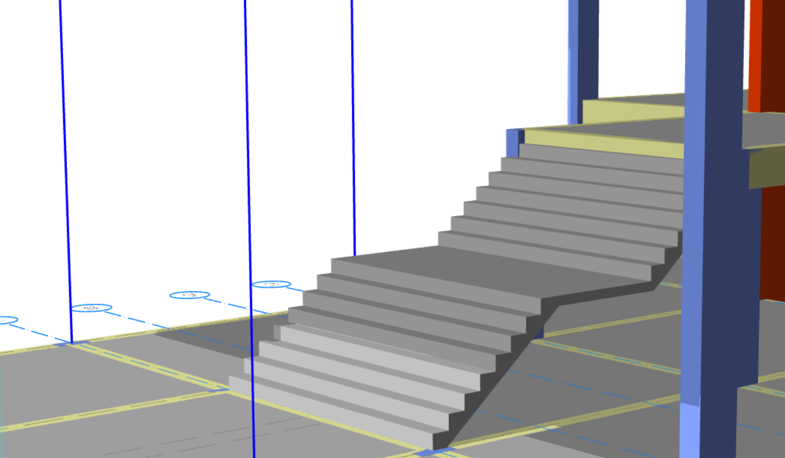
RC Staircase Module
Introduction
First and foremost, we are very excited to introduce our new reinforced concrete staircase module. Moreover, this innovative module—which is the result of our dedicated work—allows you to model reinforced concrete staircases interactively and seamlessly integrate them into the building model using a library of frequently used staircase types.
Additionally, by clicking on the “Staircase” command in the Modeling menu, you can add any type of reinforced concrete staircase to your building model by selecting one of the three methods offered and easily adjust the staircase loads. Furthermore, ProtaStructure also allows you to model staircases with finite element shell elements and include them in the building analysis model.
Finally, detailed information about ProtaStructure’s RC staircase module is provided in the attached document.
RC Staircase Module Liability and Intellectual Property
Limitation of Liability: Prota Software Inc. shall not be held liable for any losses arising from documentation errors, software defects or misuse. It is the user’s responsibility to verify all results, ensure that software operators and reviewers possess adequate technical competence, and to use the software in strict accordance with the reference manuals and documentation.
Intellectual Property: ProtaStructure® is a registered trademark of Prota Software Inc. In addition, all intellectual property rights reside with Prota Software Inc. Documentation, training materials and software components may not be copied, distributed or used in any manner that violates the license agreement.
Trademarks: ProtaStructure®, ProtaDetails®, ProtaSteel® and ProtaBIM® are registered trademarks of Prota Software Inc., as is the Prota logo.
Overview of the New RC Staircase Module
Briefly, the new RC Staircase Module enables users to interactively model common stair types from a predefined library and integrate them seamlessly into the overall building model. Moreover, future releases will expand the stair type library and introduce a “DIY Stair Editor.”
Stair Placement Interface and Methods
To begin, access the staircase command via Modeling > RC Members > Staircase. Subsequently, three placement methods are available:
Area-Based: Select a region bounded by beams, shear walls or grid lines.
Two-Point Rectangle: Define the stair footprint by specifying two diagonal corners of a rectangular area.
N-Point Polygon: Outline complex or non-rectangular footprints by clicking successive points; terminate by re-selecting the initial point.
In each method, ProtaStructure then prompts for the target area prior to creation.
RC Staircase Module Supported Stair Types
Currently, the module supports five stair configurations:
Straight: Connects two levels with a single flight.
Straight with Landing: As above, with an intermediate landing.
L-Shaped: Straight flight plus landing with a 90° turn.
U-Shaped: Two parallel flights with a 180° turn; offers additional parameters (landing depth, width, thickness) and alignment options (inner/outer).
U-Shaped with Two Landings: Two flights joined by dual landings, providing a full 180° reversal—optimal for constrained linear space or change-of-direction requirements.
RC Staircase Module Stair Parameters and Loads
Upon creation or modification, users may specify the following parameters:
Z-Offset: Vertical adjustment of the stair’s lower end.
Lock to Storey Height: Automatically match stair rise to storey elevation.
Riser Count and Tread Width.
Flight Length: Auto-computed by default; user-override permitted.
Waist Thickness: Thickness of the stair soffit.
Alignment: Position the stair within the selected area (left, center, right).
Reverse Direction: Flip the ascent direction.
Dead Load and Live Load: Uniform area loads applied as additional dead (G/D) or live (Q/L) loading.
Note: Additionally, the self-weight of the stair is calculated and applied automatically.
Stair Editor View Options
To enhance modeling efficiency, the stair editor provides the following view options:
Show Analytic: Toggle between the physical model and pseudo-analytic view to visualize analytical line connections. Warning: This is not a full analysis mesh; the true FE model is generated during global analysis.
Show Rebars: Display reinforcement placement in 3D, based on ProtaStructure’s rebar engine. Caution: This feature is in development and may not reflect final detailing.
Show Axis: Display the project grid.
Show Reference Drawing: If an architectural reference drawing is loaded on the active storey, it appears beneath the stair geometry to aid accurate placement.
Editing Stairs and Assigning Loads
Modify Stair: Select a placed stair, then right-click Properties to reopen the editor and adjust parameters.
Load Assignment: In the editor, specify additional dead or live loads. These are automatically assigned to the corresponding load cases. Custom vertical and lateral cases may also be defined; however, only temperature and uniform area loads are applicable to stairs.
Finite Element Modeling of Stairs
Importantly, ProtaStructure models stairs exclusively with FE shell elements as integral components of the building analysis mesh.
Warning & Disclaimer: Inclusion of stairs in the building analysis is debated. Because stairs connect two levels, they may introduce lateral restraint. Consequently, some engineers opt to exclude stairs from the analysis mesh—and design lateral systems as though the stairs are absent—to capture worst-case behavior. Furthermore, stairs may crack or yield under seismic load and should not be relied upon for lateral resistance.
If you do not intend to analyze stairs within the global model, do not model them here. For standalone stair design and detailing, use the ProtaDetails stair module. Additionally, when stairs abut shear walls, ProtaStructure assumes a monolithic connection. In practice, anchorage lengths may be insufficient; to simulate this, model a small gap between the stair and wall.
Integration of Slabs into the Building Model
Moreover, a slab meshing option exists under Building Analysis > Model Options > Slab Model to mesh floors for direct load distribution or diaphragm behavior. Regardless of this setting, stairs are always meshed. If slabs remain unmeshed while stairs are meshed, ProtaStructure attempts to support the stairs—but for a more realistic model, mesh slabs in the global analysis. In scenarios where beams or shear walls support the stairs, slab meshing is optional, provided you verify analytical connectivity.
Stair Design Workflow
As described above, stairs are modeled as FE shells and integrated into the global analysis. Consequently, ProtaStructure automatically extracts critical results for each stair component and generates slab strips for design.
Additional Resources
For additional guidance or technical support, please contact Prota Software Inc. In addition, you can find more resources and practical examples on the Prota Software Community Page. This page includes Webinar Recordings, a Project Gallery, and our YouTube Channel.


