Steel Base Plate Connections
Introduction
Base plates play a critical role in steel structures by providing a stable and reliable interface between steel columns and their supporting foundations. These structural members ensure the safe transfer of loads from the steel column to the concrete foundation, allowing for even distribution of forces while preventing local failure or excessive stress concentrations.
In ProtaStructure 2026, we have developed a Steel Base Plate Design Tool, a powerful addition to the structural design toolkit. This tool enables engineers to analyze the necessary failure modes for base plates, ensuring a safe and efficient connection between steel columns and foundations. The analysis is specifically tailored for cast-in anchors, with no anchor reinforcement considered for simplicity. Designed for flexibility, the tool allows users to perform calculations based on their preferred design standards, supporting Eurocode, Turkish Code, and American Code.
In the attached document, how base plates are inserted to the model, the features of the Base Plate Editor, and the design and analysis processes are explained in detail.
This document provides a detailed briefing summarizing the primary themes, key concepts and factual content from the “ProtaStructureDesignGuide-SteelBasePlateConnections.pdf” source.
Introduction & Disclaimer
ProtaStructure Design Guide v1.0 focuses on steel base-plate connections. Prota Software Inc. disclaims all liability for losses arising from errors in documentation, software defects or misuse. It is the user’s responsibility to verify all results, ensure operators and reviewers have adequate technical competence, and use the software strictly in accordance with the reference manuals and documentation. ProtaStructure® is a registered trademark of Prota Software Inc.; all intellectual property rights reside with Prota Software Inc.
Importance & Purpose of Steel Base Plates
Steel base plates provide a stable, reliable interface between steel columns and supporting foundations. They:
Safely transfer axial loads, shear forces and bending moments from column to concrete footing.
Ensure even force distribution to prevent local stress concentrations or premature failure.
Provide structural stability by minimizing movement under lateral loads or moments.
Securely anchor columns via anchor bolts, resisting excessive deformation or pull-out.
Key design parameters include plate thickness, material properties, anchor layout and edge distances—all of which directly affect connection performance, durability and safety. The ProtaStructure 2026 Base-Plate Design Tool enables engineers to analyze failure modes for cast-in anchors (excluding anchor reinforcement for simplicity) and supports calculations per Eurocode, Turkish Code and American standards.
Inserting Steel Base Plates
Steel base plates may be inserted under individual or multiple columns.
Single-Plate Insertion:
Select the steel column.
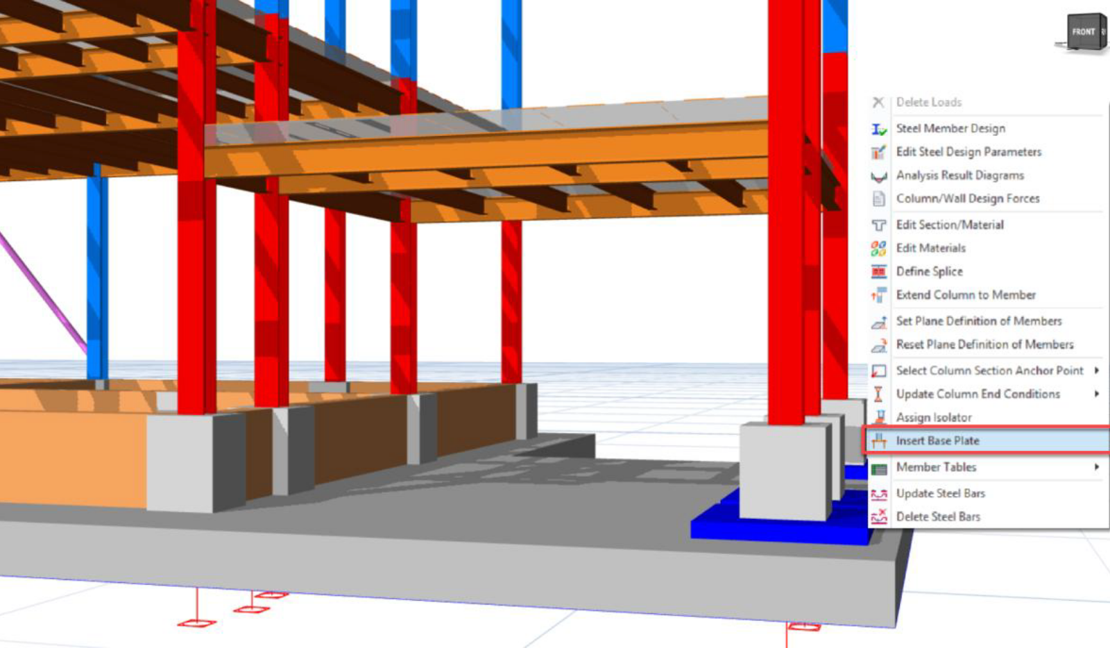
Right-click and choose Insert Base Plate, or use Modeling > Steel Members > Base Plate.
Note: The plate will be designed for the critical internal forces of that column.
Multi-Plate Insertion:
Use any selection method to pick multiple steel columns.
Right-click and choose Insert Base Plate, or use the ribbon command.
Note: All selected columns receive plates designed for their respective critical forces and are managed as a group (select, modify or delete together).
Base Plates & Structural Analysis
Since design checks depend on column analysis results, perform a structural analysis before designing any base plates. Although plates can be placed without analysis, design cannot proceed and results will not be available—plates will display only graphically.
Insertion at Foundation Level:
On RC Pedestals: Use when the steel column does not bear directly on a footing slab or beam; insert an RC pedestal below the column first.
Direct on Footing/Wall/Slab: When the column sits on a foundation element, ProtaStructure auto-detects the adjacent element and places the plate accordingly.
Note: To place plates on pad-footings, pile caps or strip footings, first insert an RC pedestal for uniform load transfer and corrosion protection.
Insertion on Other Storeys:
Base plates may be placed under steel columns on any storey, not limited to foundations—for example, onto concrete columns, shear walls, beams or thickened slabs.
Base Plate Editor
Invoked via Insert Base Plate, the editor dialog organizes design parameters into:
Structural Components: Plate size & material, anchor layout, stiffeners, shear lugs and welds.
Design: Load cases, internal forces and moment definitions.
Analysis Results:
Results: Lists all failure modes, utilization ratios and pass/fail status.
Report: Configures and generates a customized design report.
Center Panel: Dynamic input area for detailed parameter entry.
3D Visualization: Real-time model of plate, anchors and column interface.
Plate Types Gallery: Preset layouts for anchor patterns, stiffeners and load transfer schemes.
Action Buttons: OK (accept), Revert Changes (reset) or Cancel (exit without saving).
Structural Components:
Base Plate & Placement: Define plate material, length, width, thickness and edge distances.
Anchor & Stiffener Properties: Specify bolt diameter, grade and stiffener dimensions (visible when selected).
Foundation, Shear Lug & Weld: Configure shear transfer mechanism; if no shear lug is chosen, shear loads distribute between anchors and plate friction.
Base Plate Design
Internal Forces & Moments:
The Design menu allows review and selection of internal force combinations under various load cases to ensure the plate will safely resist applied actions. Features include:
Duplicate Selected Force: Manually enter custom force values.
Select All / Deselect All: Quickly include or exclude load combinations.
Critical Analysis Results: Highlight governing load cases.
All Analysis Results: List every available combination for manual selection.
User-Defined: Add and edit bespoke combinations.
Analysis Results
Results divide into two panels:
Results:
Design Check: Dropdown listing each failure mode, governing code clause and formulation.
Utilization Ratio: Capacity usage percentage (values >100% indicate failure).
Status: Green check for pass; red warning for fail.
Report:
Select desired report components before clicking Generate Report:
Design Results Summary: Consolidated pass/fail overview.
Material Report: Listing of material properties.
Geometry Report: Plate, anchors, welds, pad-fillers and stiffeners summary.
Internal Forces Report: Forces, moments and selected load cases.
Design Results: Utilization ratios and statuses.
Detailed Design Results: Full calculation breakdown with code references and formulas.
Batch Design
Design all or selected plates in one interface via Design > Steel Designs > Base Plates. The batch table shows:
Design All / Design Selected (use CTRL for multi-select).
Close / Cancel actions.
Plate Label & Column Label assignments.
Plate & Anchor Bolt Properties, Embedded Length.
Design Status & Governing Check for each entry.
Conclusion
The ProtaStructure suite delivers a comprehensive toolkit for designing steel base-plate connections. For questions or technical support, contact globalsupport@protasoftware.com or asiasupport@protasoftware.com and you can find more resources and practical examples on the Prota Software Community Page. This page includes Webinar Recordings, a Project Gallery, and our YouTube Channel.


