

Plane Properties
|
Plane Definition | "Plane Properties" will be loaded when the "Plane Definition" option in the "Modelling" ribbon is selected. Planes are used to assist adjusting the levels of the members in Z direction. |
Plane definition is a particularly efficient way of modeling structural members such as sloping slabs (e.g. ramps) that are not parallel to the plan level in the building.
To define a new Plane:
1. Press “Plane Definition” button  in "Modelling" ribbon.
2. The “Plane Properties” form will be loaded. You can change the label of the Plane member by using up and down arrow at the right of the “Plane No:” field. 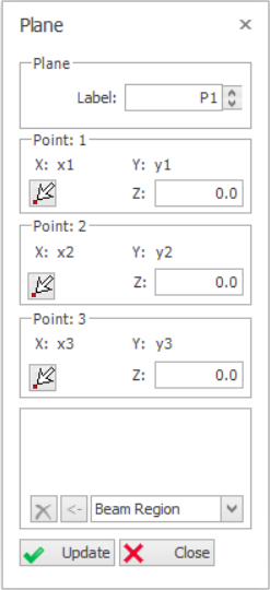
3. There are five options to define the Plane member, namely, “Axis Region”, “Beam Region”, “Pick Points”, “Pick Closed Slab Edge”, and “Pick Axis”.
- In order to get detailed information about these methods, you can watch this video : Slab Insertion Options.
4. After inserting the Plane member using one of the five methods mentioned above, coordinates of the three corner points of the plane member will be shown in “Point: 1 ", “Point: 2 ” and “Point: 3” fields.
- "Point: 1” will be assigned to the Left-Bottom corner of the plane by the program automatically. Starting from “Point: 1”, other corner points of the plane will be determined in an counter-clock wise order.
- As it’s known from the mathematics four points are necessary for the equation of a plane. 4th corner point is calculated internally and will not be shown in these fields.
5. When plane member is first defined, all the values in the “Z” fields will be zero. This means that plane is parallel to the storey level and at the same level.
- If you enter a positive value to the “Z” field of a corner point related corner point will be raises by that amount relative to the storey level.
Editing an Existing Plane Member
In order to edit an existing plane:
- Select an existing plane.
- Right-click and select “Properties”.
- Modify the fields such as “Z” in the “Plane Properties” form.
- Press the "Update" button in the “Properties” form or Right-click and select “Update” option in the Shortcut Menu.
You can repeat this process on as many planes as you wish. One plane at a time can be edited by this method.
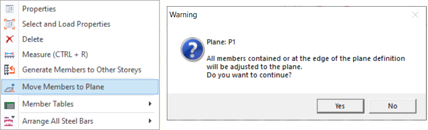
Move Members to Plane Definition
One of the most commonly used options in the Planes shortcut menu is “Move Members to Plane Definition”.
It is used after the level of the corner points of an existing plane have been adjusted by using “Z” fields.
In order to use this option:
- Select the Plane in which the level of the corner points have been adjusted.
- Use “Move Members to Plane Definition” option in the shortcut menu by right-clicking in order to adjust all of the structural members contained or at the edge of the plane to the new plane level.
 Users can refer to the example in How to model inclined / sloping slab for steps to model slanting slabs using plane definition.

Please note that if Plane Definition is applied around a wall, the Wall Model Type should set to
FE Shell Model. This is to ensure connected members are properly support by the wall.