How To Model A Foundation At Different Level Or Storey
What is a default support? Default Supports Method
The support provided by default is dependent upon the storey level at which the column or wall stops.
For columns and walls that stop at ST: 0 (i.e. the foundation) — Default = Fully Fixed Support (Show in below figure, boxed in red)
For columns and walls that stop at level above ST: 0 — Default = No External Support (Show in below figure, circled in green)
In order to model foundation elements at different level, you can use User Defined Supports Method .
User Defined Supports
These can be applied to the lower end of any column or wall at any level to introduce an external support or spring. The translational (in global X, Y and Z) and rotational (about global X, Y and Z) degrees of freedom can be set to fixed, or free, or a spring stiffness can be assigned.
Unless you specify and apply user defined supports, every column and wall in your model adopts a default support.
When might a default support not suitable to use?
In typical models you will often find that default supports are all that is needed. However, certain situations might require you to specify and apply user defined supports.
Cases where user defined supports could be necessary include:
Buildings with spring, or pinned supports
Buildings with stepped foundations (different elevation)
Specifying a User Defined Support
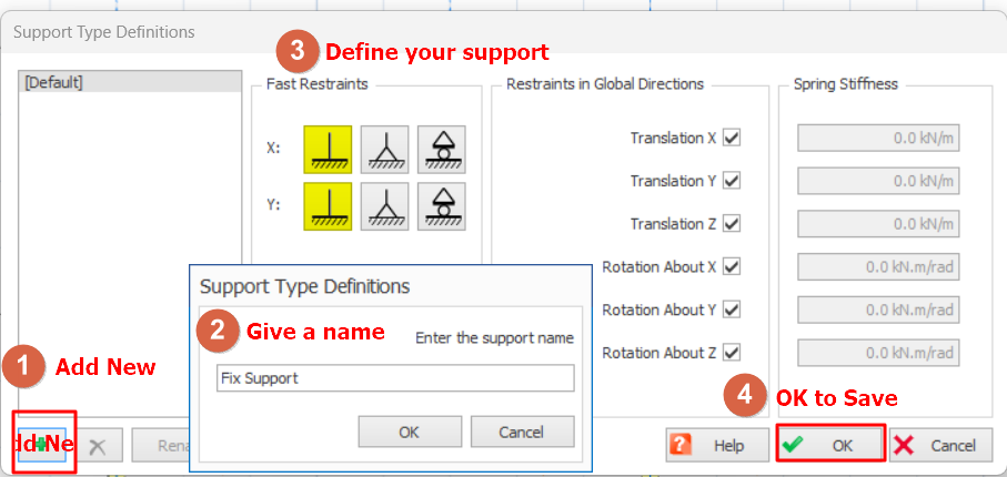
User Defined support can be defined as example follows:
Choose Support Typefrom the Modelling Tab (top menu).
Click the Add New button and enter a label to describe the new support type.
To define a translational release in a particular direction, uncheck the x, y or z support box as appropriate.
To define a rotational release in about a particular axis, uncheck the X‐Rotation, Y‐Rotation or Z‐Rotation support box as appropriate.
To define a translational spring in a particular direction, enter the spring stiffness in the appropriate x, y or z box, (having first unchecked the corresponding support box).
To define a rotational spring in a particular direction, enter the spring stiffness in the appropriate X‐Rotation, Y‐Rotation or Z‐Rotation box, (having first unchecked the corresponding support box).
Click OK to save the new support definition.
Applying a User Defined Support
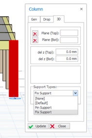
Having defined a new support type as above, it can then be assigned to a specific column or wall using the member properties dialog:
Select and load the properties for the column or wall.
Click on the 3D tab and choose the appropriate Support Typefrom the list.
Click on Updateto save the change.
User Defined Supports ‐ Trouble shooting
In models where you have applied user defined supports, we would recommend that you carefully review the analysis results to ensure they are working as you intended. Careless application of supports could have unexpected effects.
Mechanisms A mechanism may be introduced if, for example, you have applied a pinned support to a pin ended member.
Diaphragm restraint Typically, a rigid diaphragm exists within the floor slab. Hence, if a slab connects to the base of a column which has a user defined support applied, the support will be directly restraining the rigid diaphragm itself. This could inadvertently prevent lateral displacements from developing at that level even if this was not the original intention.
Load Paths User defined supports are assumed to transfer any reaction directly to the foundation. You should not apply a user defined support at an upper storey level unless there is means for this transfer to occur.
A stepped foundation is an example of where a user defined support would be appropriate, whereas, a transfer column situation (i.e. where the column is supported by another member) is an example of where it is not.
Example of User Defined Support Method
Pilecaps/Footings can be modelled at different level/storey according to steps below:
1. Create a new support type via Modelling tab(Top menu) > Support Type
2. After a new support type is created. Assign the newly created support type to the corresponding columns in the column properties (refer to snapshot below).
Please take note, you can only access to column properties in ST:01 and above.
3. For column base level that stops between storey, you may create columns at the higher level, set del z (Bot) to meet the level and Support Types to your defined support.
4. Run Building Analysis and go to analytical model to check all the displacements & forces (ie. moment, shear, axial load) to ensure the column is correctly supported.
5. You can now go to ST:01 select columns and right click to insert the pilecap/footing.
We use cookies to run the site, understand how it is used, and — with your permission — to measure our marketing. You decide which cookies to allow. Read our Privacy & Cookie Policy.
Manage cookie preferences
Strictly NecessaryAlways Active
Required for the website to work — navigation, security, and remembering your privacy choices. These cannot be switched off.
Analytics
Help us understand how visitors use the site so we can improve it. Data is aggregated.
Marketing
Used to measure our advertising and show you more relevant content across websites.