In most of the situation, default generated views are not sufficient. User may create additional view from different perspective using “Model View" option under View (tab).
3D View
User can create a new 3D view directly by selecting " 3D View
" command. Once click, a new 3D view will be created. To adjust the view boundary, user may go to "View Properties" for setting.
Plane View
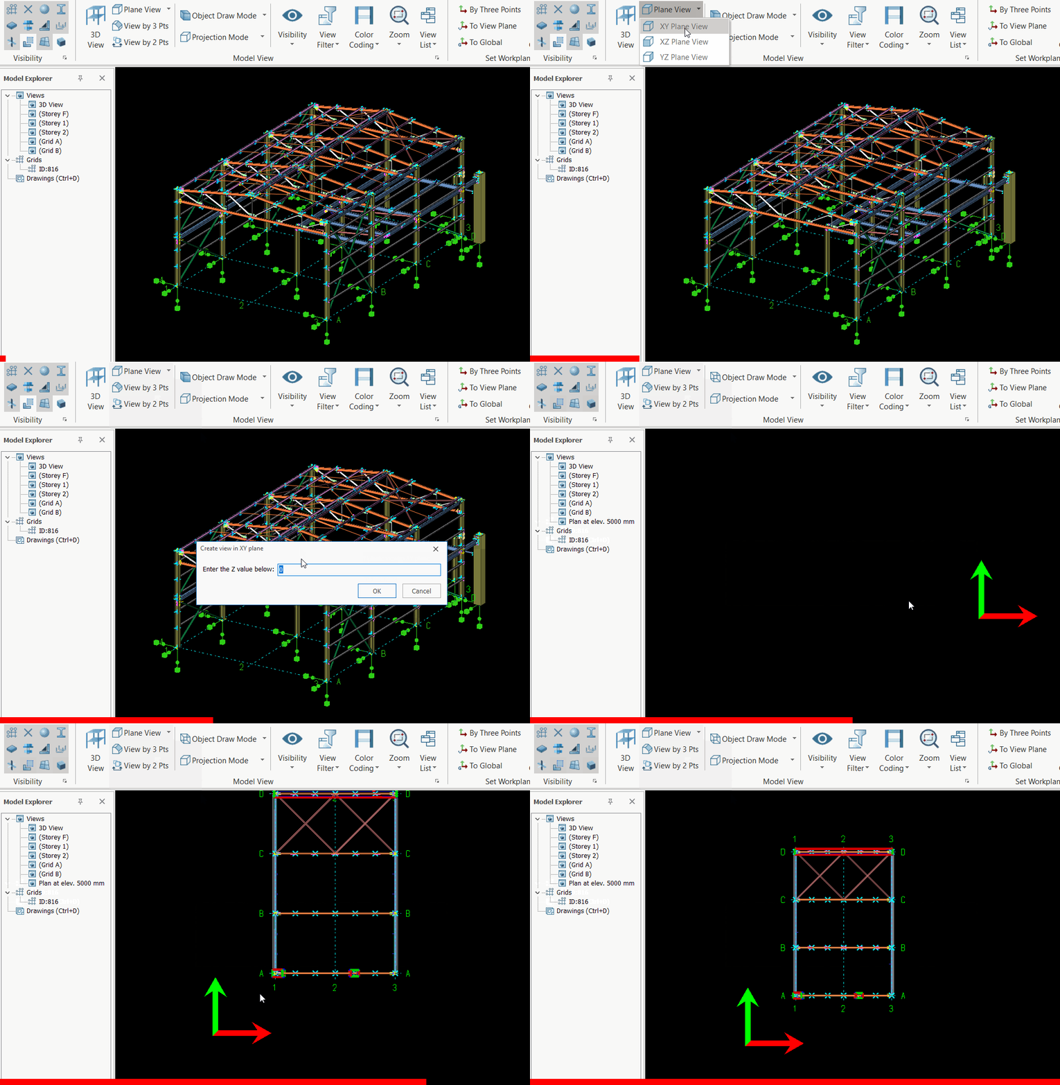
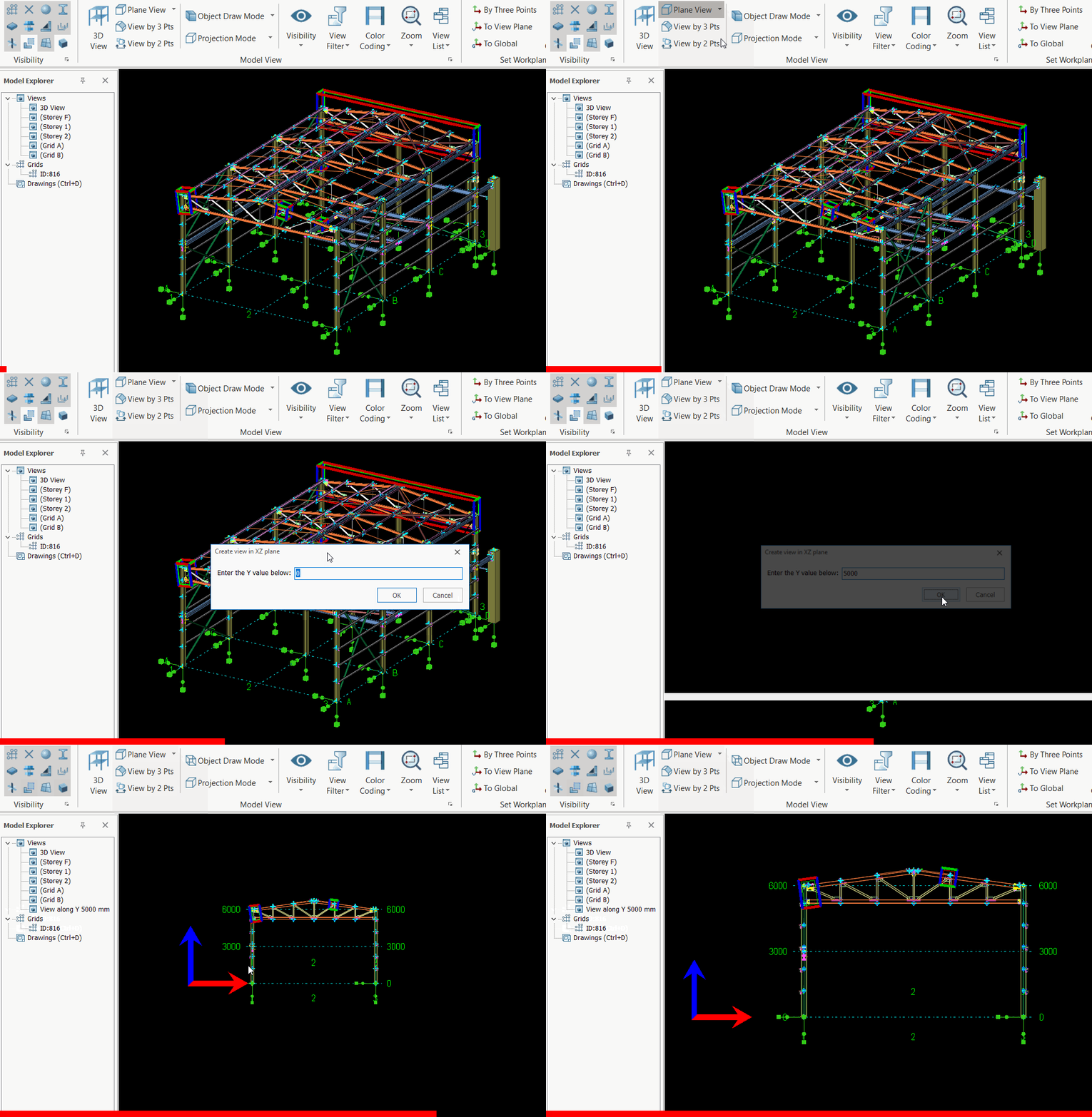
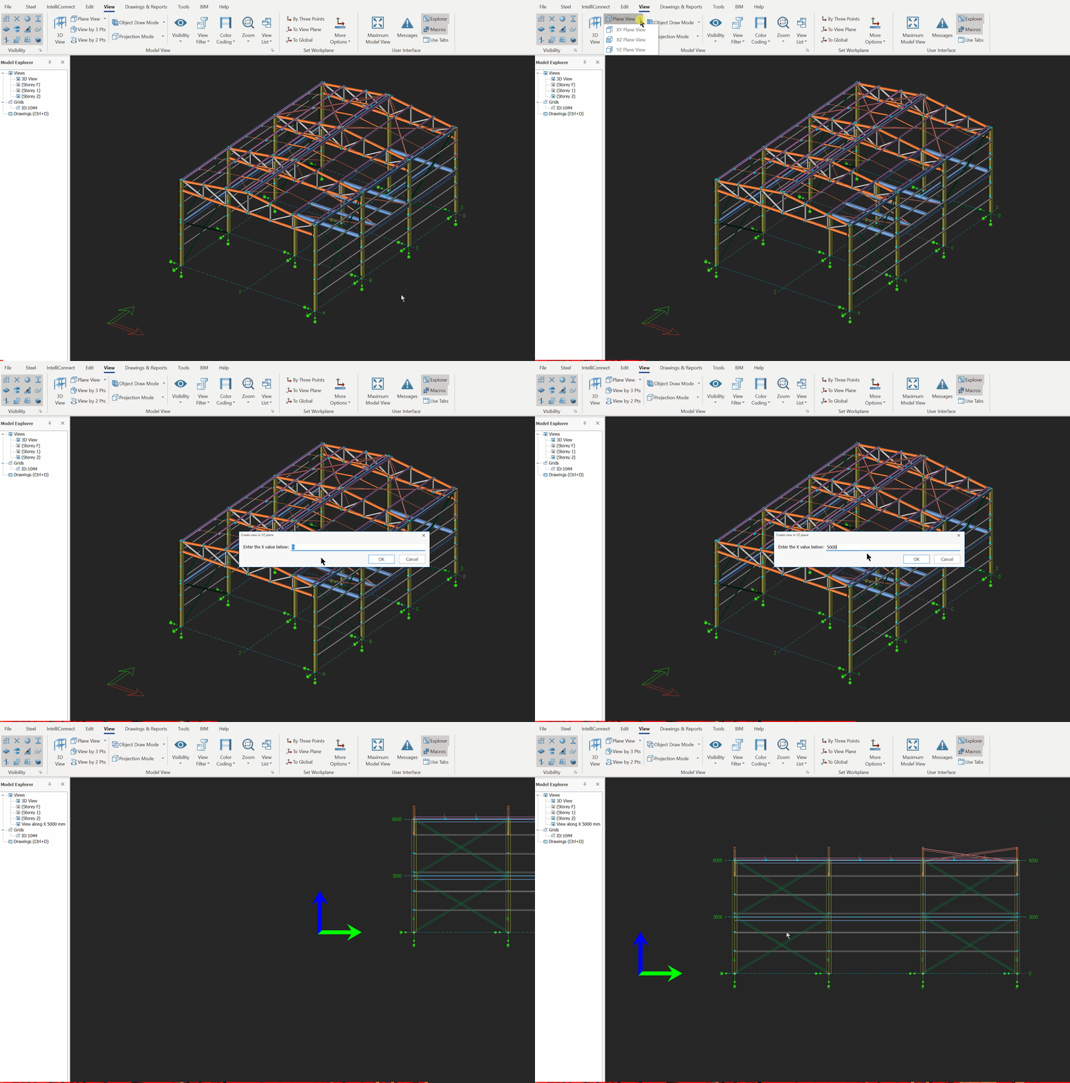
User can quickly create an 2D view directly from any existing view by key in the distance from the origin using these 3 options:
XY Plane View
XZ Plane View
YZ Plane View
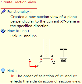
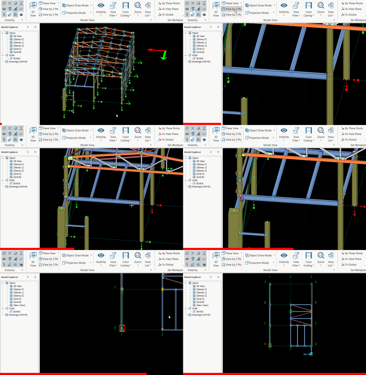
Create View by 2 points
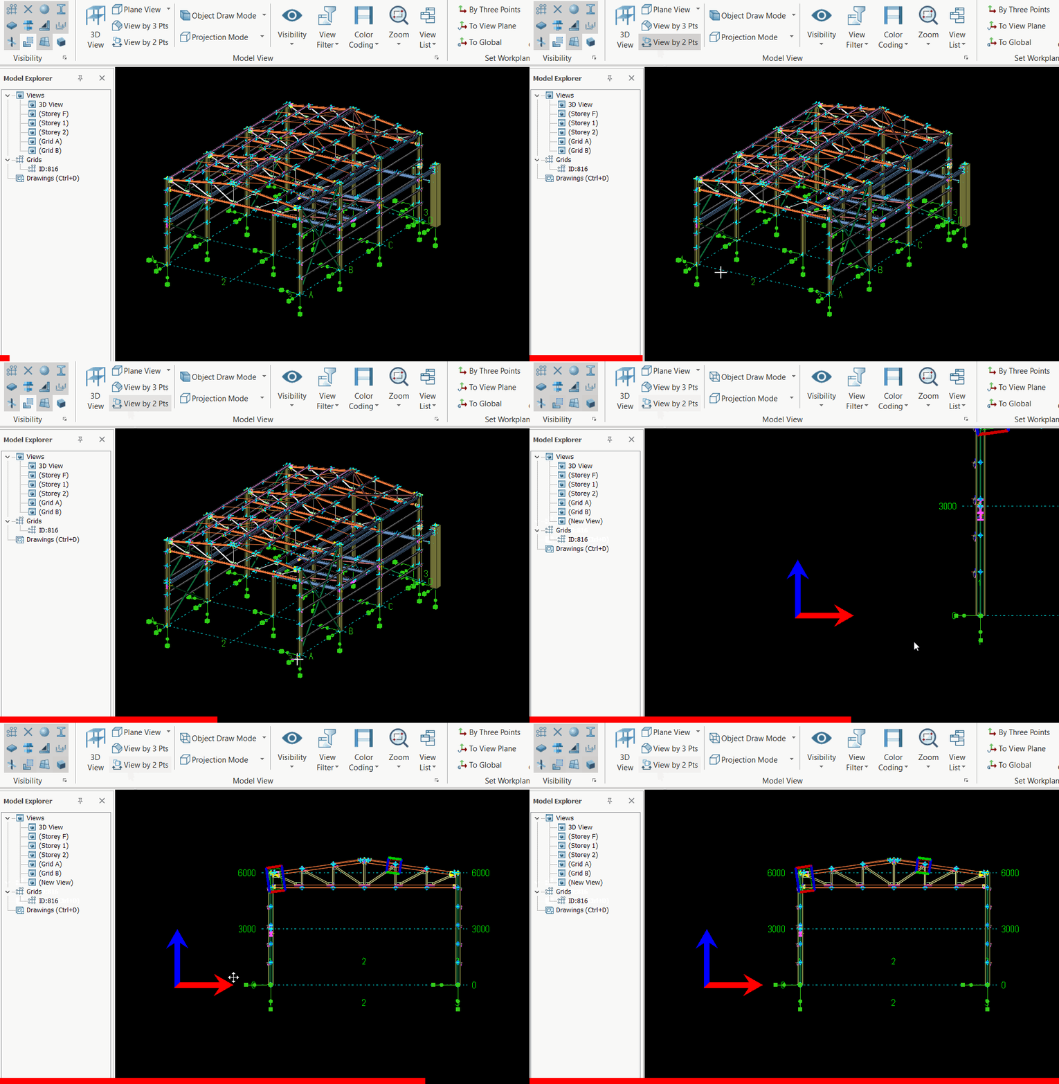
User can quickly create an elevation view directly from any existing view by selecting specific nodes :
Go to View (tab) > View by 2 Pts
Pick Point 1 & Pick Point 2
A new sectional view will be created
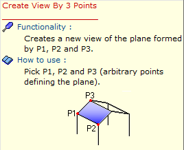
Create View by 3 points
User can quickly create a 2D plan or elevation view directly from any existing view :
Go to View (tab) > View by 3 Pts
Pick Point 1, Point 2 & Point 3
If point 3 picked vertically from Point 1, then elevation view will be created, whereas point 3 picked horizontally from Point 1, then plan view will be created.
A new view will be created
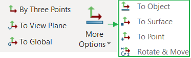
Set Workplane
Since many commands in ProtaSteel depend on a coordinate system to work, you should set an appropriate coordinate system. By default World Coordinate System is the active work plane. To learn more about coordinate systems and workplanes read Overview of Coordinate System & Workplane Concept.
Set Active Workplane to a View’s Original Work Plane
To set the active workplane to a View’s Coordinate System (VCS) use theSet Current Workplanecommand on that view’sToolbar Tab.
Set Active Workplane to Global Coordinate System
To set the active workplane to World Coordinate System (WCS) use theSet Workplane to Globalcommand on a view’sToolbar Tab.
User Coordinate System (UCS)
In addition to WCS and VCS, users can define single coordinate system which is independent of views or WCS. This is calledUser Coordinate System.
User can not create multiple User Defined Coordinate systems at a moment. In other words, when the user creates another user defined coordinate system, the previous user defined coordinate system is replaced with the new one.
Create a User Defined Workplane
An user defined workplane can be created as follows:
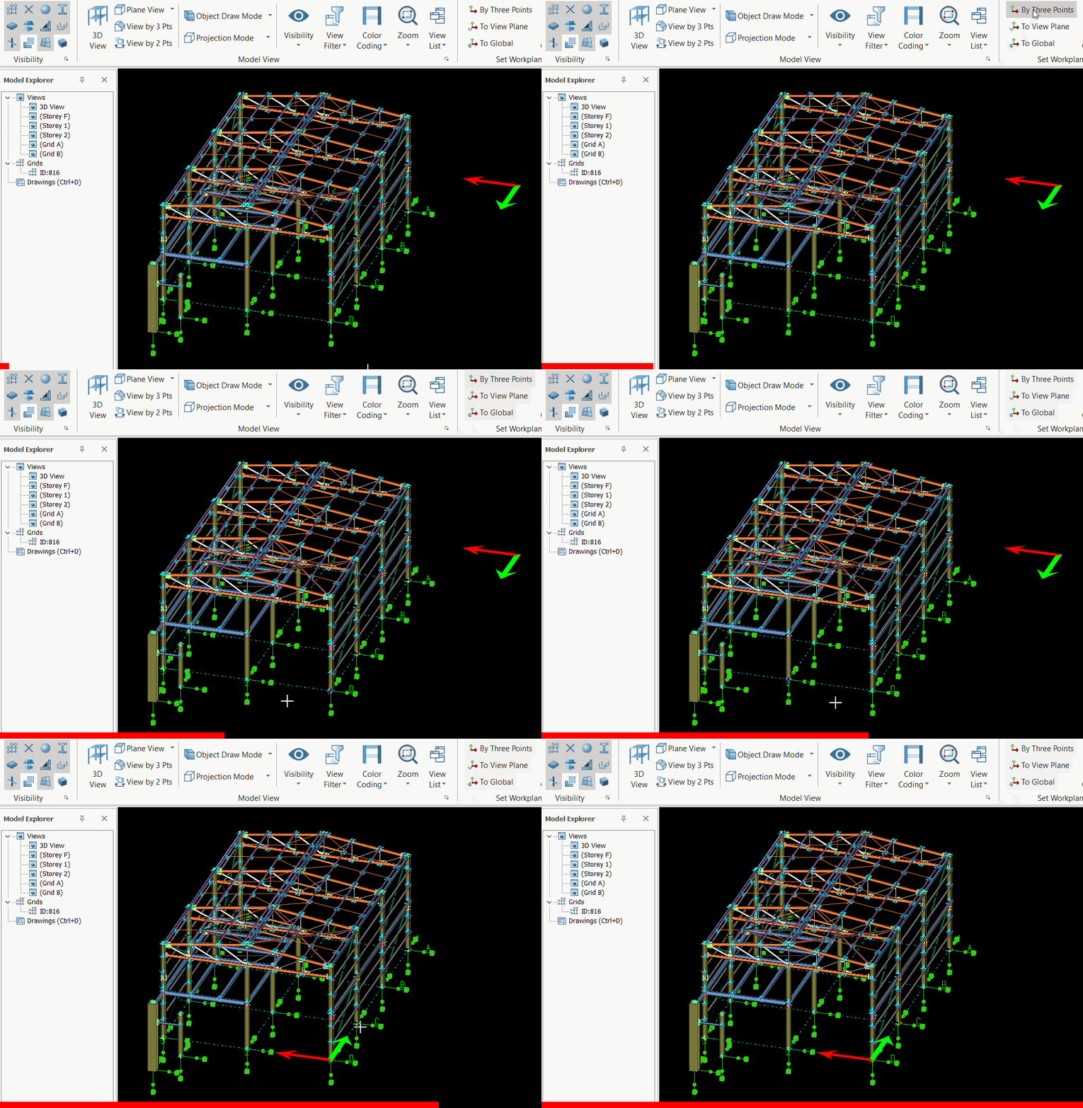
Click the Set Coordinate System by 3 Points from View (Tab) > "Set Workplane" toolbar group.
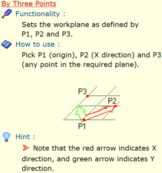
Select the first point (P1). This point becomes the origin point of the new coordinate system.
Select the second point (P2). Note that as you move the cursor, a red arrow is displayed from first point to the cursor which indicates the X-axis of the new coordinate system.
Select the third point (P3). A green arrow is displayed before picking third point. This green arrow indicates an auxiliary vector in the XY plane of the new coordinate system.
We value your privacy
We use cookies to run the site, understand how it is used, and — with your permission — to measure our marketing. You decide which cookies to allow. Read our Privacy & Cookie Policy.
Manage cookie preferences
Strictly NecessaryAlways Active
Required for the website to work — navigation, security, and remembering your privacy choices. These cannot be switched off.
Analytics
Help us understand how visitors use the site so we can improve it. Data is aggregated.
Marketing
Used to measure our advertising and show you more relevant content across websites.










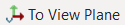 command on that view’s Toolbar Tab.
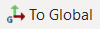 command on a view’s Toolbar Tab.