

Double-click any place within the Viewport blue border to access the Viewport Properties
The viewport properties mainly controls the final presentation of the drawings. There are several tabs in this dialog
General tab

- Name : This will the name of the viewport and the name will be shown at the bottom of the viewport (if desired)
- Modelling View ID & Modelling View Name : These show the ID and Name of Modelling View used for this viewport. (non- editable)
- Boundary : Shows the boundary coordinates of the border (non- editable)
- Scale : Scale of the viewport.
-
Offsets (X,Y) : Used to adjust the position of the model relative to viewport.
- The origin is exactly at the middle of the viewport.
- Positive X moves the model to the right; Negative X moves the model to the left
- Positive Y moves the model to the bottom; Negative Y moves the model to the top
- The origin is exactly at the middle of the viewport.
- Rotations : Applies rotation to the model about X, Y & Z axis respectively
- Use bolt faces for Hidden Line Removal (HLR) : When this is checked, bolt faces will block all the hidden line (visually unseen).
- Fix viewport center during resize : When this is checked, viewport will be remain centered during resized.
- Do not delete viewport : Lock viewport will stop user from deleting this viewport.
- Fit button : Automatically position the model and resize the viewport size to fit the model
- Fit Settings button : Select object types to be fit
- Re-import All button : Re-import all viewport & will cause the drawing to re-created
- Import (Update) button : Update the viewport
-
Draw Mode
- Line : Draw all elements as single lines
- Wireframe : Wireframe outlines only. Hidden & non-hidden objects will be shown as continuous lines
- Hidden line : Hidden objects will not be shown
- Full Dashed : Hidden objects will be shown as dashed lines (default recommended setting)
- Line : Draw all elements as single lines
-
Collapsible :
- Enable : check the box will enable members to collapse, i.e. squeeze more into the view by automatically cropping long members shorter
- Min. Collapse Size : Input the minimum collapse size for the viewport
- Min. None Collapse Area Size : Input the minimum none collapse size for the viewport
- Enable : check the box will enable members to collapse, i.e. squeeze more into the view by automatically cropping long members shorter
Label Settings tab
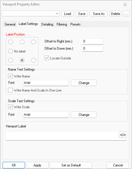
A automatic label and scale can be inserted with a viewport. The Label Settings tab controls this.
-
Label Position : select the desired position of the label
- Offset to Right (mm) : adjustments in offset horizontal distance to the position of label
- Offset to Down (mm) : adjustments in offset vertical distance to the position of label
- Locate Outside : Check to place the label outside the viewport border
- Offset to Right (mm) : adjustments in offset horizontal distance to the position of label
-
Name Text Settings
- Write : Check the box to show the Name of the viewport
- Font : Click "Change" to select the font and text height
- Write : Check the box to show the Name of the viewport
-
Scale Text Settings
- Write : Check the box to show the Scale of the viewport
- Font : Click "Change" to select the font and text height
- Write : Check the box to show the Scale of the viewport
Detailing tab
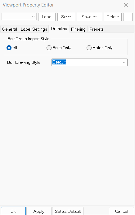
The detailing tab mainly control how bolts are drawn.
-
Bolt Group Import Style
- All : Show bolts & holes
- Bolts Only : Show bolts only
- Holes Only : Show holes only
- All : Show bolts & holes
-
Bolt Drawing Style
- Default : Bolts drawn to scale
- Line : Bolt will be drawn as cross + (Easier to view at elevation)
- Line Symmetric : Bolts drawn as symmetric cross + (Easier to view at elevation)
- Default : Bolts drawn to scale
Filtering tab
The Filtering settings controls the view extents and objects shown.
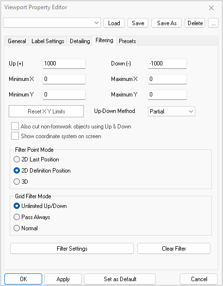
- Up (+) : Sets the upper boundary of depth of visibility ( 0 = infinite)
- Down (-) : Sets the lower boundary of depth of visibility (0 = infinite)
- Minimum X,Y & Maximum X, Y : Sets the boundary of visibility in the view plane (0 = infinite)
- Reset XY Limits : Reset XY limits value to default
-
Up-Down Method
- Partial : only elements partially in the described region are also displayed
- Full : only elements which are fulling in the described region are displayed
- Partial : only elements partially in the described region are also displayed
-
Also cut non-formwork objects using Up & Down : non formwork object will be cut by the boundary
-
Show coordinate system on screen : To show coordinate system
-
Filter Point Mode (control visibility of points)
- 2D Last Position
- 2D Definition Point
- 3D
-
Grid Filter Mode (control visibility of grids)
- Unlimited Up/Down
- Pass Always
- Normal
- Unlimited Up/Down
-
Filter Settings
- Reveals additional Filter Options such as object types, eg. grid, bolt, weld, etc
- Reveals additional Filter Options such as object types, eg. grid, bolt, weld, etc
Presets tab
The presets tab allows user to save the settings as re-use them.
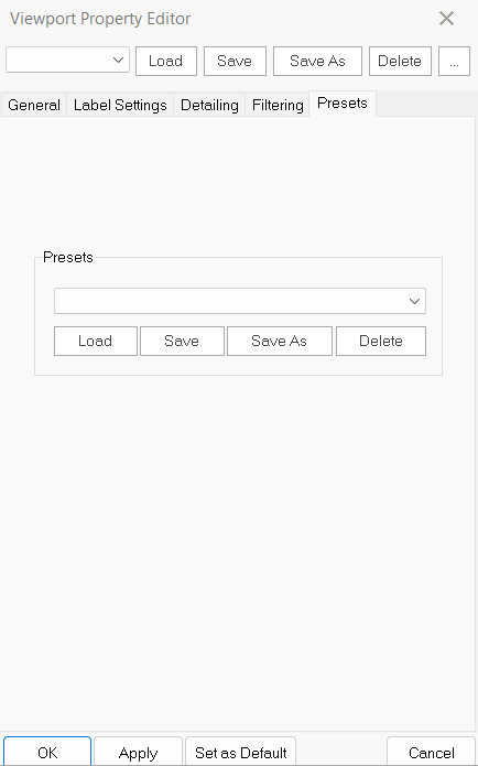
- Load : Load the preset selected
- Save : Save to the current selected preset
- Save As : Save current settings as a new preset
- Delete : Delete the selected preset