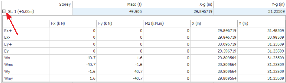
Lateral loads can be applied at each floor level of the analysis model, or individual Column/Wall nodes (Joint loads that can be assigned to individual columns/walls are not limited only to lateral loads). You can use the “Wind and Storey Load” to define horizontal loads applied at each floor level.

For example, if the wind loads calculated manually are larger than the notional loads, you can enter them here. In this case, the entered value will be shared between rigid diaphragms and free nodes on that storey by their mass ratios.
Torsional effects due to eccentricity will be handled by applying a torsional moment on diaphragm master joints and free nodes if exist.
Lateral loads acting on storey levels can be seen and modified in “Wind and Storey Load” located on the “Pre-Analysis” page of “Building Analysis” form. The “Wind and Storey Load” consists of two tables.
- In the upper table storey masses and centers of gravity are displayed. The lower table displays lateral load cases used in the analysis with magnitudes of forces and application points.
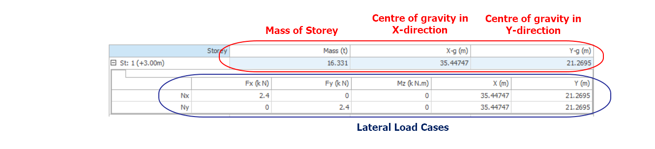
- Depending on the storey selected in the upper table, the force and application point values will differ. Also depending on the lateral load case type used, the force values may or may not be edited.
- For example, notional horizontal loads are automatically calculated based on the Code chosen and hence cannot be edited. Wind load cases are manually created and hence can be edited.

Values written in these cells are for whole storey. For Notional Horizontal load, Eccentricity can be applied by entering the Eccentricity value in the Lateral Loading dialog. Forces and moments due to eccentricity are applied automatically at the gravity centers of each diaphragm.

If there is more than one rigid diaphragm or free nodes on the storey level, this load will be shared proportional to their masses.
Storey masses and mass centers are calculated during the building analysis process. After a modification to the building model, masses and mass centers will be calculated again if building analysis is repeated.
Wind Load Input and Analysis
There are 3 methods of defining lateral or wind loads:
Method 1: Storey Load Editor
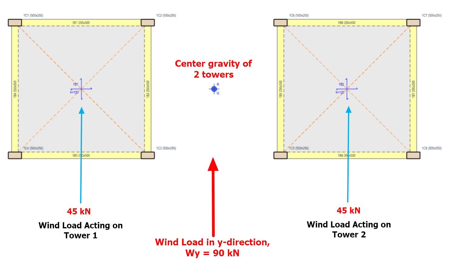
If you want to insert wind load using Storey Loads Editor then Wind load should be applied at the centre of building elevation (see figure below).
ProtaStructure will automatically distribute the wind load to the centre of diaphragm of each tower – the magnitude of the distribution is proportional to the mass of each floor. Tower with bigger members and larger slab would have a higher mass and hence will attract more wind load.
The wind loads, namely Wx and Wy are defined as point loads on each storey. The coordinates (X, Y) of the applied wind loads are measured from (0, 0) – NOT from the bottom left corner (axes intersection) of the model.
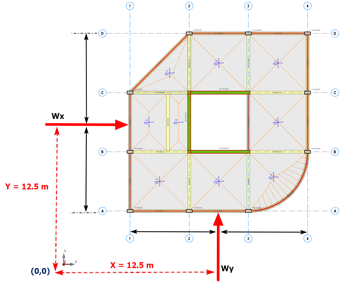
The Notional Horizontal Loads are applied at the centre of mass (CG) of the floor, whereas the Wind Loads should be applied at the centre of the building elevation.
See example below assuming that the 2 towers have the same mass.
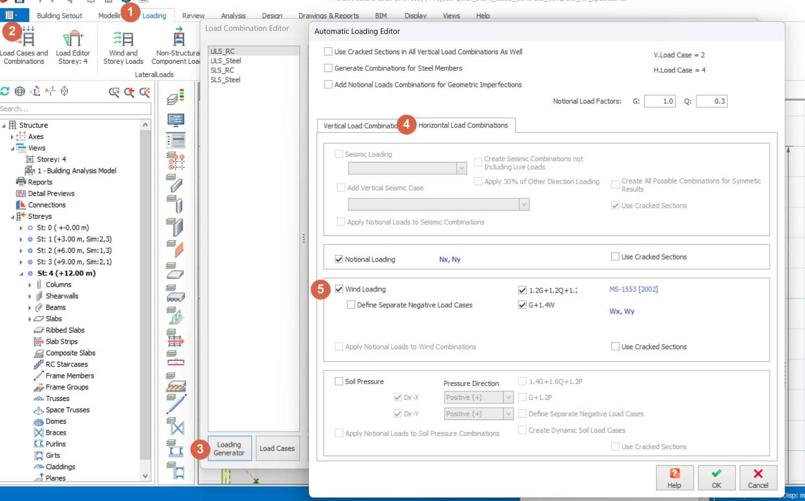
- In order to add Wind Load to the model, you should generate the Wind Load Cases and Load Combinations: Loading tab > Load Cases and Combinations > Loading Generator > Horizontal Load Combinations > Check the Wind Loading
- To apply the Wind Load to each storey: Building Analysis > Pre-Analysis > Wind and Storey Loads
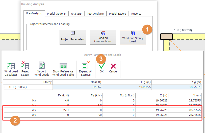
- The distribution of the wind loadings on both towers is as shown below:
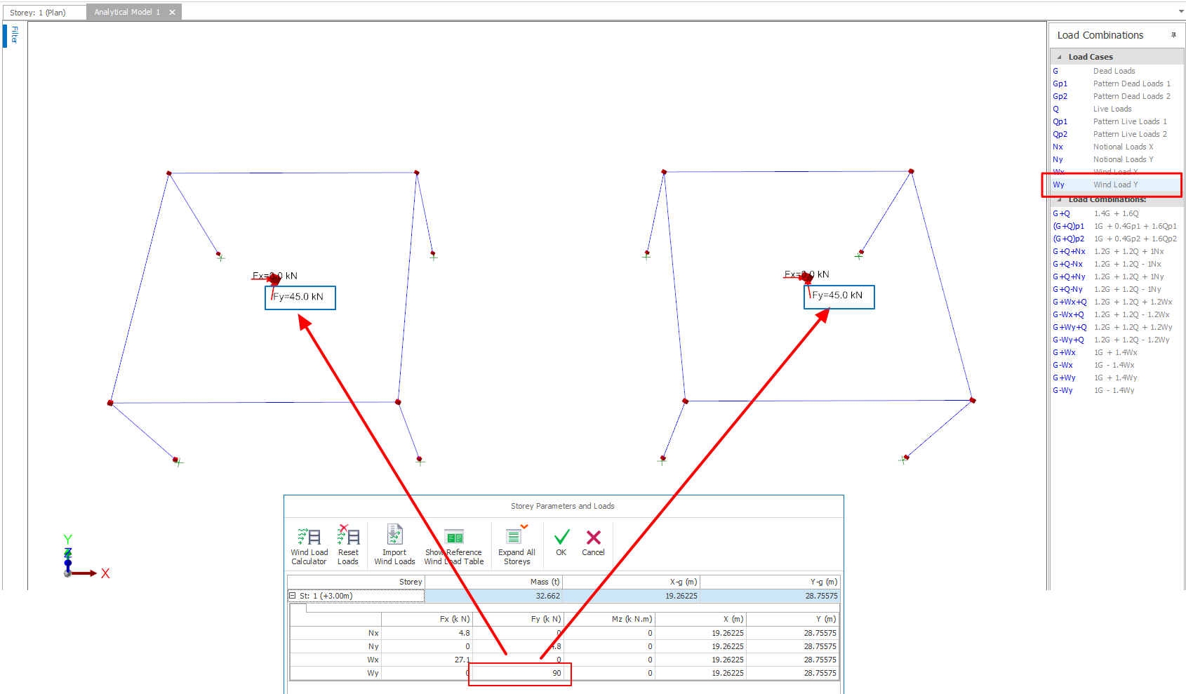
- To check the exact magnitude of wind load applied on each tower, you would need to go to the Post-Analysis > Display Analysis Results > choose the load case Wy and then look at the nodal loads applied (as shown below)
The 2 towers will still behave independently.

The limitation of this method is that you cannot control the value of load on each tower. The value of load is based on mass of each storey which is automatically calculated by the program. Floor with higher mass will attract more wind load.
If you want more control then the other method is to apply wind loads onto specific columns.
Method 2: Through Load Editor Tab
This method is to apply wind loads on the node of the columns, walls, claddings, etc. using Load Editor.
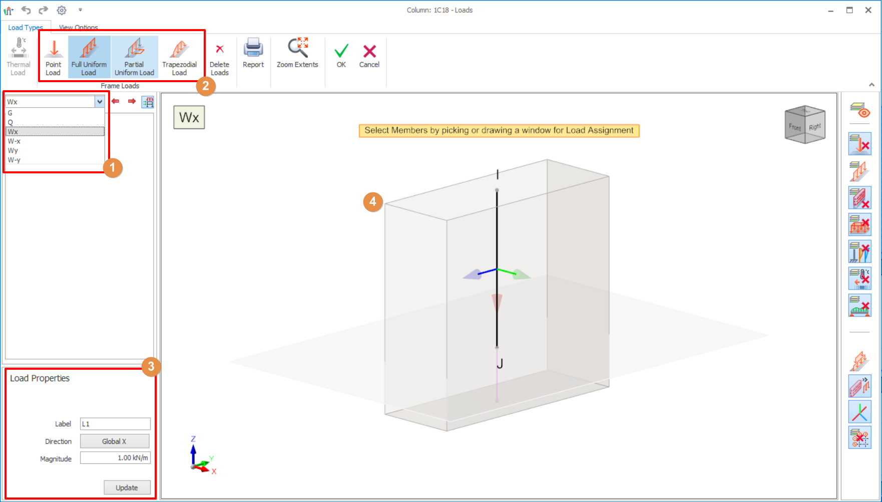
- Select Wind Load cases.
- Select Load Types
- Set direction and magnitude of the loadings.
- Insert the loadings in 3D view.
For more details of load editor, kindly refer to Load Editor
Method 3: Automatic Wind Load Calculator
The wind load calculator allows the automation of wind load calculations and application to the ProtaStructure multi-storey structures. The wind load calculator automatically calculates the wind forces in accordance with the chosen wind code and applies it to building structure. This greatly increase productivity as values need not be manually calculated & entered. The wind code of practice covered are:
- BS6399-2 (1997)
- MS1533 (2002)
- EN1991-4 (2005) – Singapore/ Poland Annex
- ASCE7 (2010)
- Thailand Wind Code (2012)
- NSCP Wind Code (2015)
How to Use
Step 1: Define Wind load combinations:
- In Loading tab, click Loading combinations button
- In Load Combination Editor, click Loading Generator button
- In Automatic Loading Editor, go to Horizontal Load Combinations tab > Check Wind Loading as shown below
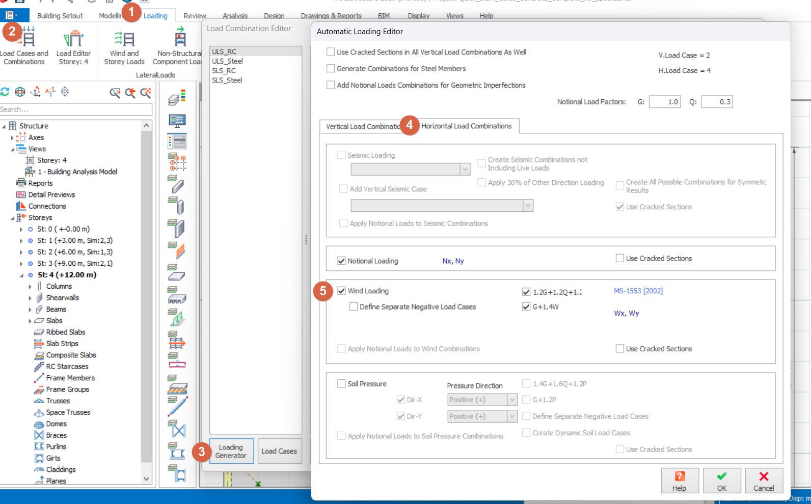
Check “ Define Separate Negative Load Cases ” if the wind acting from left to right & right to left is expected to be different, e.g. irregular shaped building. Additional wind load cases Wx+, Wx-, Wy+ & Wy+ will be created.
- Click OK to close Automatic Loading Editor dialog
- Click OK to close Load Combination Editor dialog
Step 2: Calculate and Apply Wind Loads:
- In "Pre-Analysis" tab, click "Wind and Storey Loads" button
- Click Wind Load Calculator in Storey Parameters and Loads dialog to launch the wind load calculator
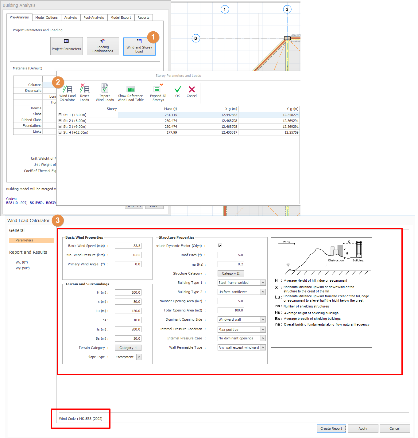
- Most parameters are illustrated and explained in the right figure.
- "Primary Wind Angle" can be used to adjust the direction of the primary wind angle. The effective building width and length will be calculated accordingly. Direction factor will be applied where applicable.
- All other parameters are explained in the respective codes of practices.
- If there are basements that are not subjected to wind loads, it can be excluded via Edit Storey dialog (Building Setout top menu) > Input No. of Rigid Basements
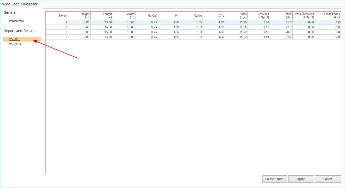
- Click the wind load cases in the Report and Results in the left pane to review the calculated wind pressures and wind loads (as shown below)
- Click "Create Report" button at the bottom to generate the wind load summary report
- Click "Apply" at the bottom right to apply the wind loads to the model
- Review the applied wind loads in the "Wind and Storey Loads".
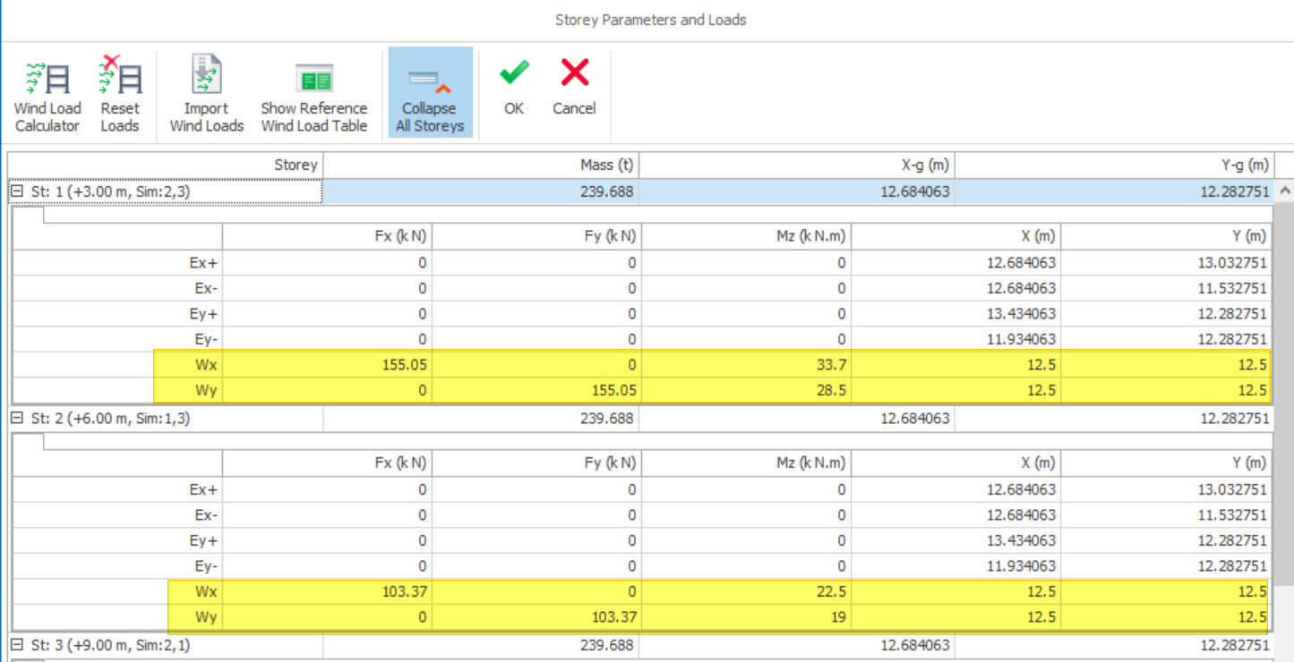 The applied wind loads are editable, you may click & edit the applied wind load.
 - Click OK to close Storey Parameters and Loads dialog.

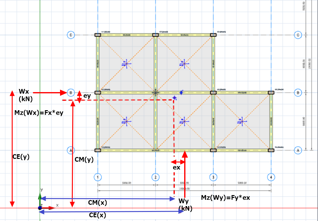
When automatic wind load is used, Mz which is the torsional moment on the floor is automatically calculated, based on the following explanation :
- The auto-calculated wind load entry is at the center of elevation (CE) of the building in the direction under consideration, i.e. X & Y coordinate column.
- However, in analysis, the wind load will be applied at the center of mass (CM) of the floor diaphragm, since a CM joint will be auto-created, representative of slab diaphragm constraining the movement of the floor as single entity.
- Hence, there is a need to calculate Mz to ensure the net effect is equivalent analytically.
- Let’s name the difference of CE and CM coordinate as eccentricity, ex & ey, calculated based on :
- ex (x-direction) = CE (x) – CM (x)
- ey (y-direction) = CE (y) – CM (y)
- Mz is calculated based on Wind load magnitude multiplied by ex or ey :
- Mz (Wx) = Fx * ey
- Mz (Wy) = Fy * ex
The figure below illustrates how Mz is derived:
Step 3: Run building analysis and review the results in Post-Analysis Result Display
- Go to Building Analysis tab, click Start to perform building analysis
- Go to Post-Analysis tab, click Display Analysis Results
- Go to Elements tab, make sure the Loads and Diaphragms in the Nodal Points button group are activated (as shown below)
- Click any wind load case in the Loading tab (on the right panel).
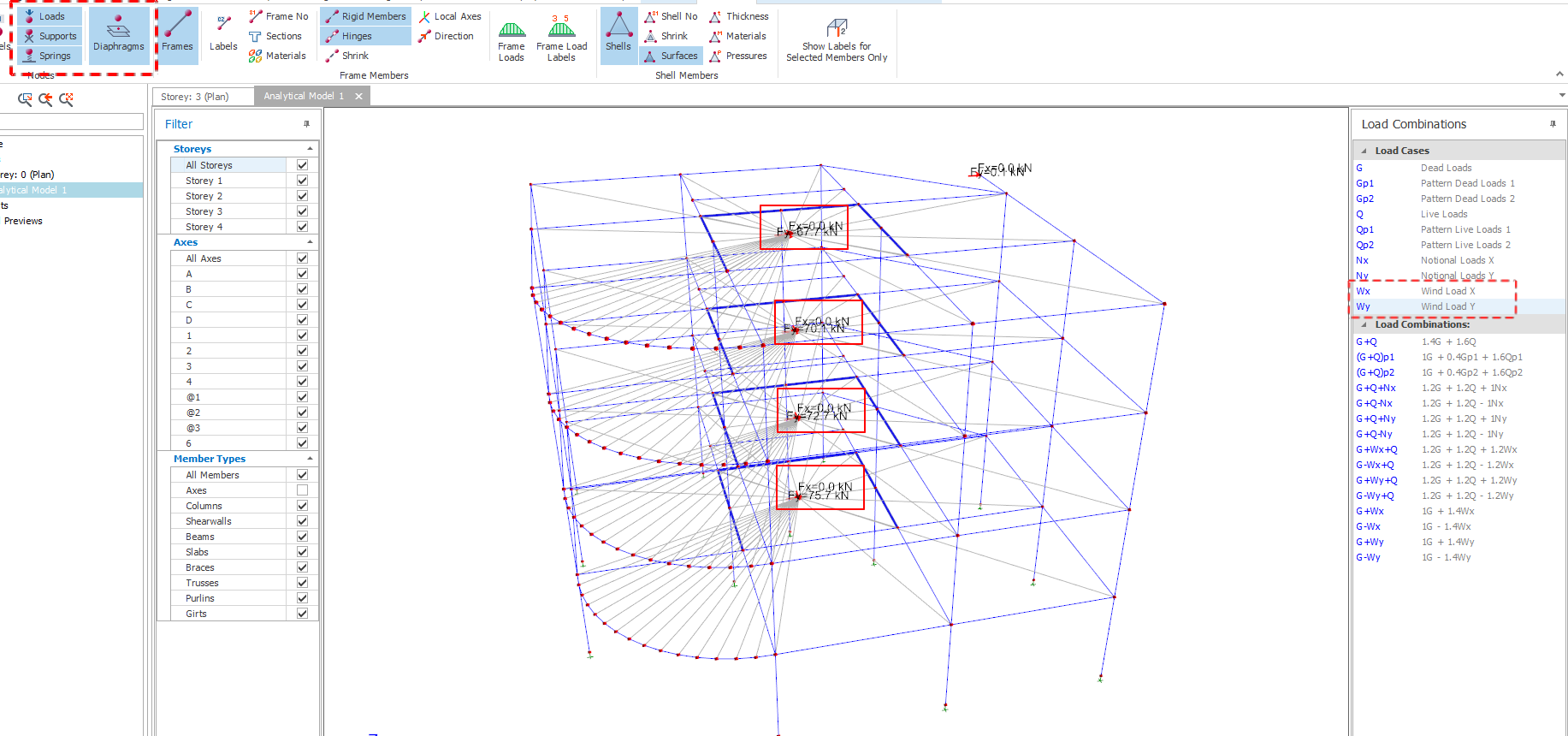
The applied wind loads will be shown as nodal point loads that are automatically distributed to the center of every floor diaphragm if slabs are modelled & floor diaphragm is considered.
If slabs are not modelled or floor diaphragm is ignored or there are isolated columns / walls not connected to the floor diaphragm, the wind load will be applied as nodal load directly on each column & wall :
- The magnitude of load applied will be proportional to column/wall mass, which is equivalent to its size on plan, since the height of all the vertical elements are the same for the same floor.
- This means that higher wind load value will be applied to bigger columns and walls.
- This is the same method used to distributed the auto-calculated Notional Horizontal Loads / Equivalent Horizontal Load.

Assumptions & Limitations
- Irregular buildings on plan (such as C shape, U shape) will be converted to an equivalent rectangle.
- Wind loads will only be calculated for windward and leeward faces to obtain the net wind pressures/loads on each elevation.
- This wind load will not, at this stage, support wind calculations of low rise industrial buildings where side and roof wind pressure calculations are required.
- The auto wind load calculation will assume all floors wind facing surface are enclosed without any opening. This means that perimeter partition wall, shearwall or opening will not affect the wind load calculation at all.
- The number, distance and dimensions of adjacent buildings in different wind directions will be taken as an average input and shall be manually calculated by the user.
- For building height exceeding 150 m to 200 m, the calculated wind loads might not be applicable. Please refer to the respective code of practice as requirements are different. A wind tunnel test should be conducted if necessary.
Wind Loads Distribution
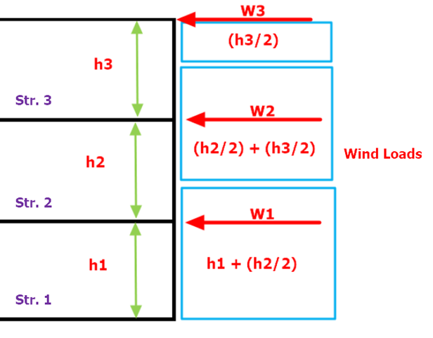
For 1st storey, ProtaStructure considers the storey’s height and half the height of the upper storey when computing wind loadings for 1st storey.
For intermediate storeys, half the height of the current storey and half the height of the upper storey will be considered.
For rooftop storey, only half the storey’s height will be taken into account while calculating wind load.
The distribution of wind loads utilized in wind load calculation is shown in the figure below:
Wind Load Import from CSV/Excel File
The wind loads can be imported from a csv / excel file. This greatly increases productivity as values need not be entered manually.
The sample csv file can be found in the default installation folder :
C:UsersUser NameDocumentsProtaLibSamples
- WindPointLoad_SampleImport.csv is used if "Define Separate Negative Wind Load Case" is unchecked in Load Combination Editor (see below).
- WindPointLoadSeperateNegativeLoadCases_SampleImport.csv is used if "Define Separate Negative Wind Load Case" is checked in Load Combination Editor (see below).
How to Use
- Open the sample file WindLoadImportSample.xlsx or csv file in Microsoft Excel
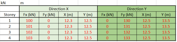
- Enter the values of the wind force Fx & Fy the corresponding coordinates X & Y for point of application, i.e. figures in red as shown above
- Save file as .csv format
- In Building Analysis menu, use Loading Generator to generate the wind load cases & combination
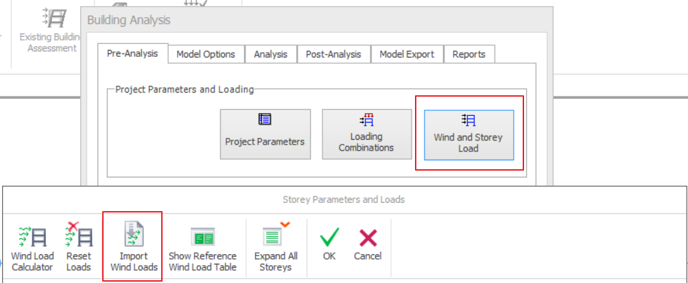
- In Building Analysis menu > Pre-Analysis Tab > click on Wind & Storey Loads button
- Pick Import Wind Loads in Storey Parameter and Loads dialog
- Select the csv file previously set-up
- Expand the storey loads inforation by click the "+" icon & check the values imported (as shown below)