

Steel Elements
In ProtaSteel, you can only create joist, purlin, girt, stair member, plates, eaves beam & sag rods. Main members such as beam, column & brace must be created in ProtaStructure.
Each type of element is defined with different command. These commands are accessible from the Steel Ribbon:

Place the mouse cursor on the command icon and read the tooltip carefully on how to use it.
All types of elements are created by clicking the appropriate icon from the ribbon and selecting two points generally. When elements are created they are positioned according to default orientation rule.
 To learn more about the default orientation rule read Overview of Coordinate System & Workplane Concept.
Elements are created with default settings, such as end releases, materials, section properties, etc. These parameters can be changed using Profile Editor which is displayed by double clicking on it. Properties of more than one element can be set simultaneously by selecting multiple elements.
Profiles of frame elements are selected from a database. Almost all standard shapes in the world exist in the profile database of the ProtaSteel.

However, if you wish to use a non-standard (arbitrary) shape or a standard shape that doesn’t exist in the profile database, it is possible to add new shapes to the profile database using the Profile database editor.
Creating Steel Elements
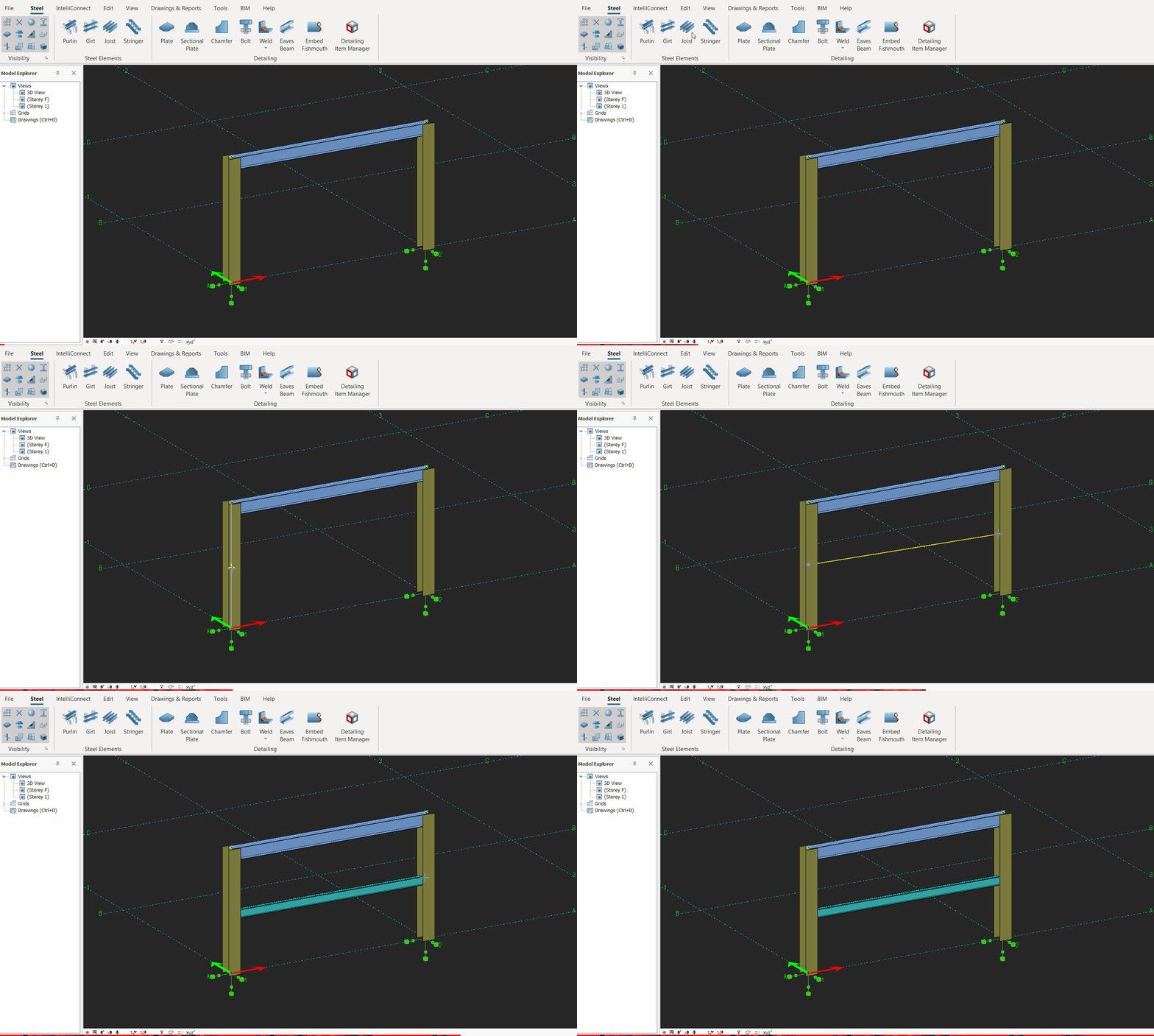
Generally, a steel element, eg. girt is creating using the following steps :
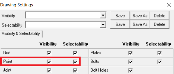
- Make sure that visibility and selectability of points are on.
- Click Frame Creation toolbar icon
- Select the start point of the element. A yellow temporary line is drawn to represent the item:
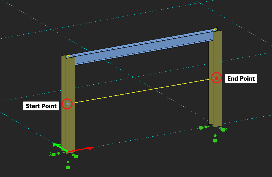
- Select the end point of the element. The element is placed according to default orientation rule.
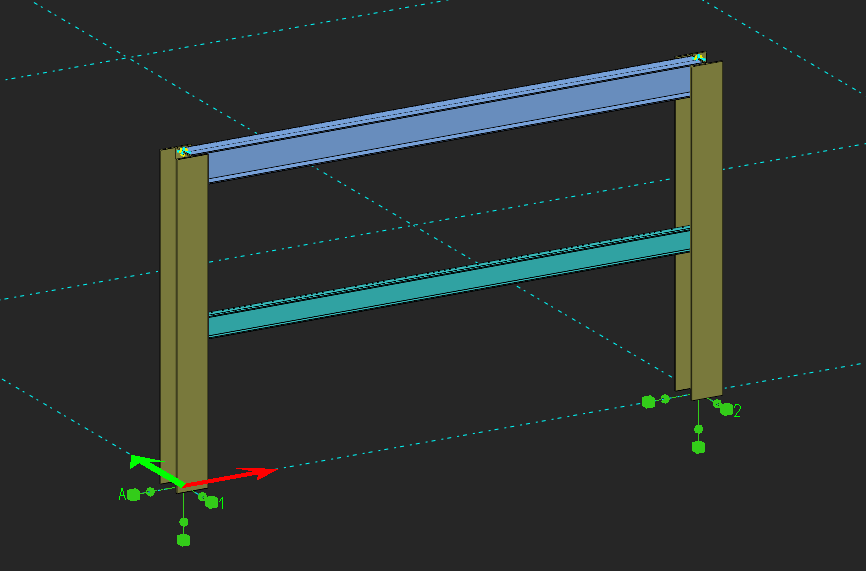

 Elements must be defined between points. However, instead of creating points you can use Fast entry mode. To learn more about creating points click here, and to learn more about fast entry mode click here.
ProtaStructure and ProtaSteel are integrated software and structural members (members such as columns, beams, braces, trusses) must be created in ProtaStructure and transferred to ProtaSteel.
However, some secondary members are allowed to be defined in ProtaSteel. Purlin, girder, joist, and staircase elements can be added to ProtaSteel as secondary members.
With the "floor beam=joist" command, both horizontal and vertical members can be created.
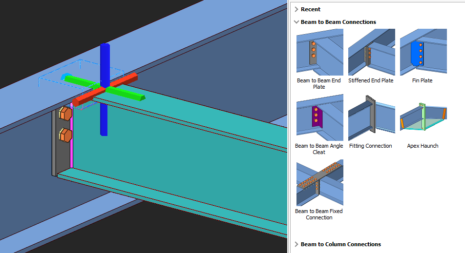
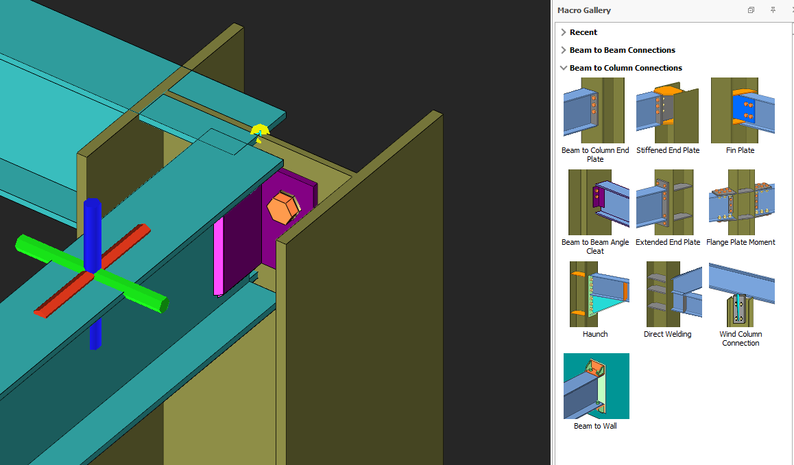
"Joist" connections can be made with some macros:
- Beam to Beam End Plate Connection
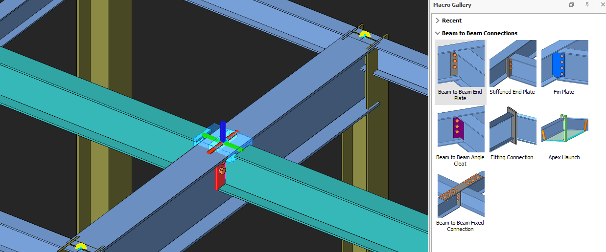
- Stiffened End Plate Connection
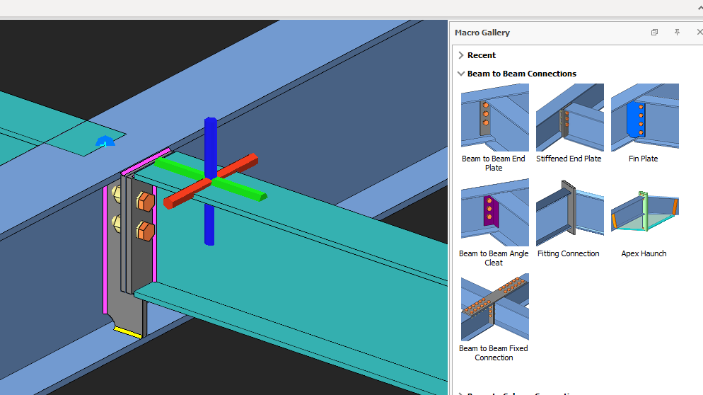
- Fin Plate End Connection
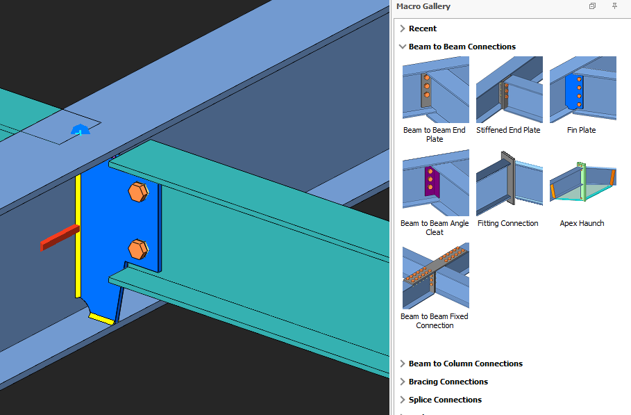
- Beam to Beam Angle Cleat
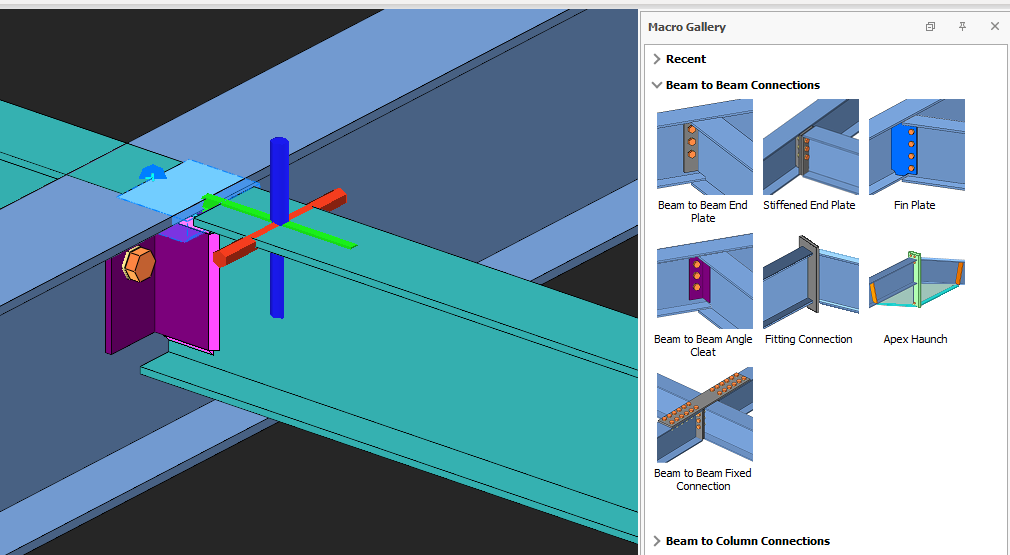
- Fitting Connection
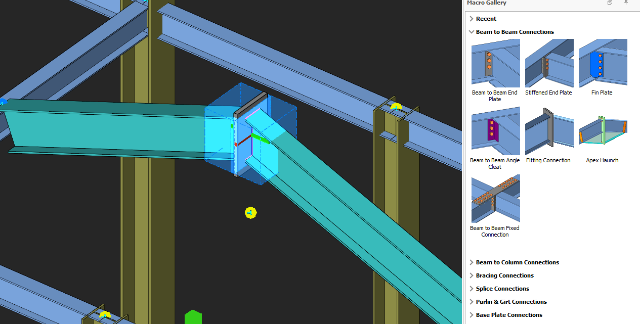
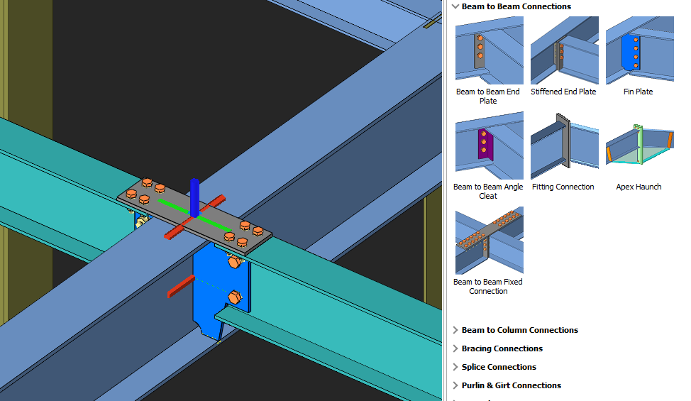
- Beam to Beam Fixed Connection
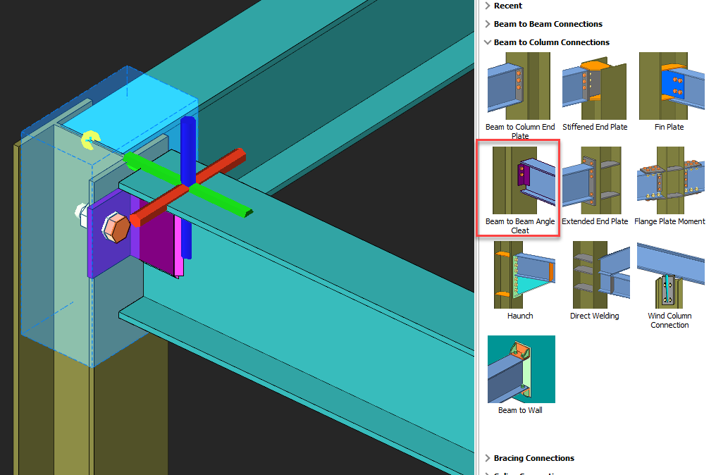
- Beam to Column Angle Cleat Connection
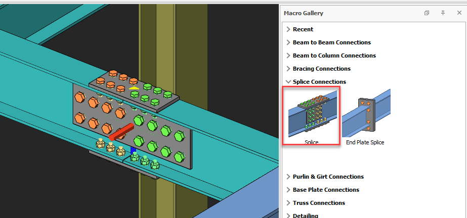
- Splice Connection
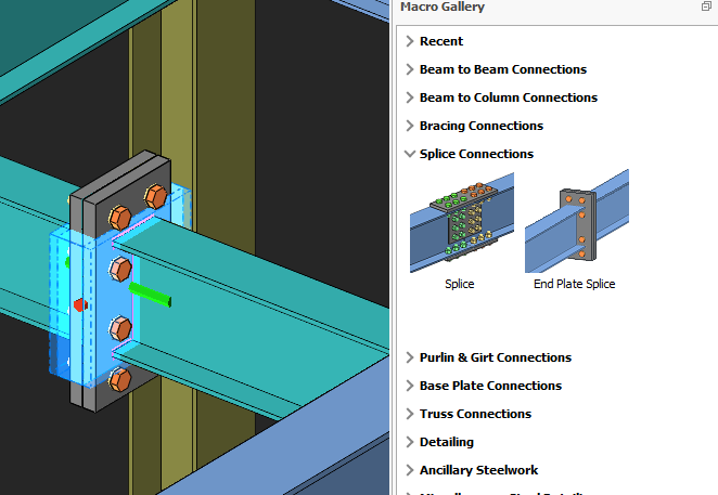
- End Plate Splice Connection
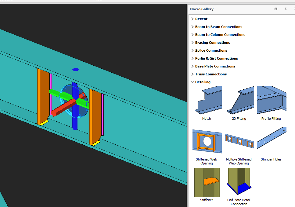
- Stiffened Web Opening Macro
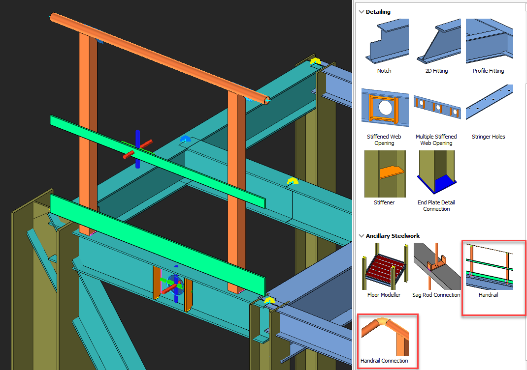
- Handrail Macro
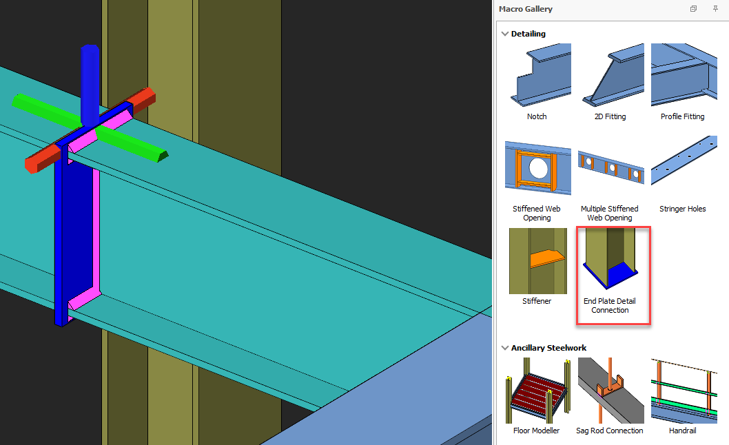
- End Plate Detail Connection
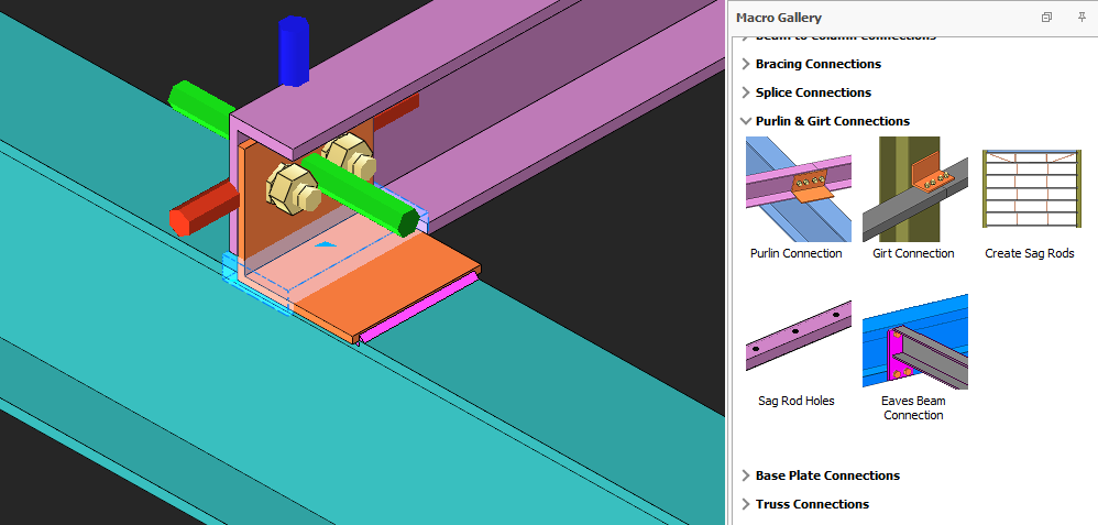
- Purlin and Girt Connection
Creating Steel Detailing
Plate
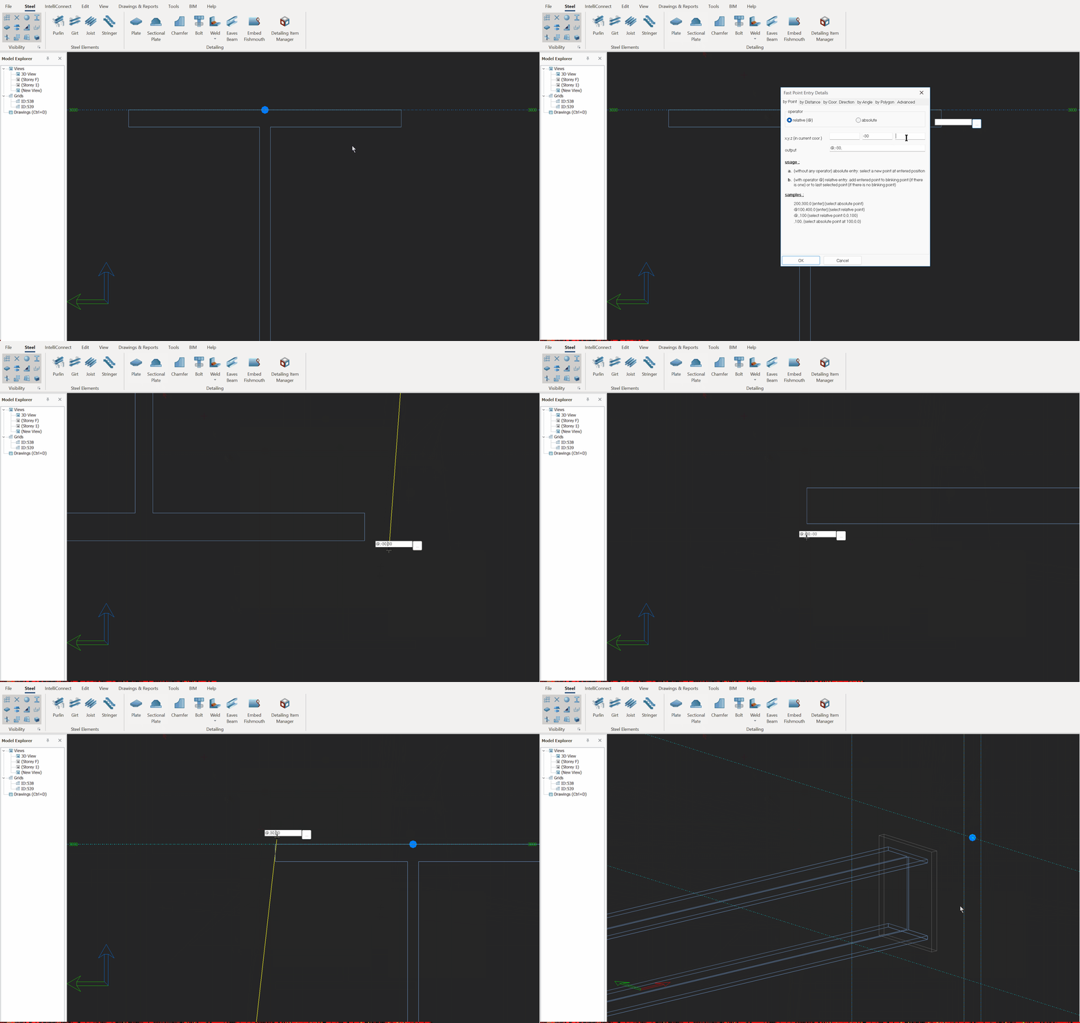
- Click on the "Plate" icon and select multiple points.
- To finalize, select the first point again.

Plate can be created using "Fast Point Entry" without create point in model. If "Fast Point Entry" is used, global axes or working plane must be identified beforehand. The red color axis is axis-X, green color axis is axis-Y and blue color axis is axis-Z respectively.
Sectional Plate
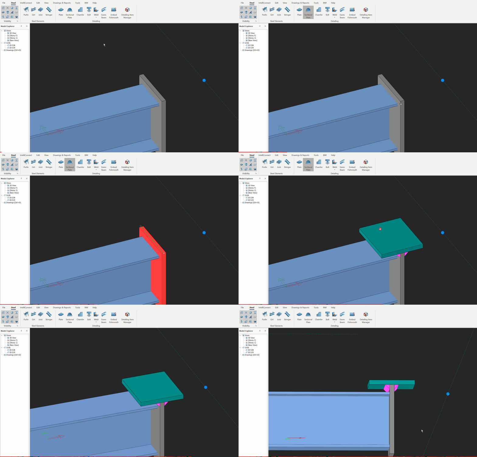
Create one-sided or two-sided sectional plate on the selected plate perpendicularly.
- Click on the icon and select a plate.
- Select two points to create the sectional plate.
Chamfer
Modifies the selected corner(s) of plate(s).
- Select corner(s) of plate(s) by "Alt+ Left Click".
- Click on the icon and set the parameters in dialog and click "Apply"
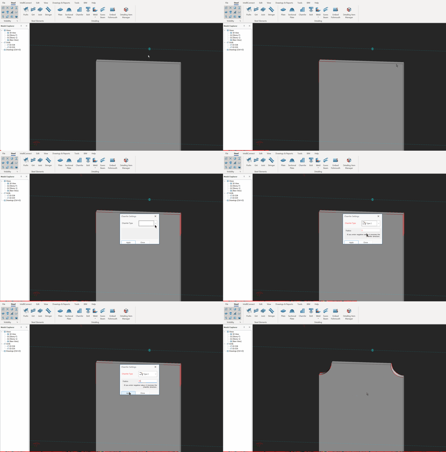

To select multiple corners, press "Alt + Ctrl + Left Click".
Bolt
- Click on the icon and select an object (e.g. plate) to be bolted.
- Right-click > select the first point to specify the start of the bolt group.
- Select second point to specify the x-direction of the bolt group.
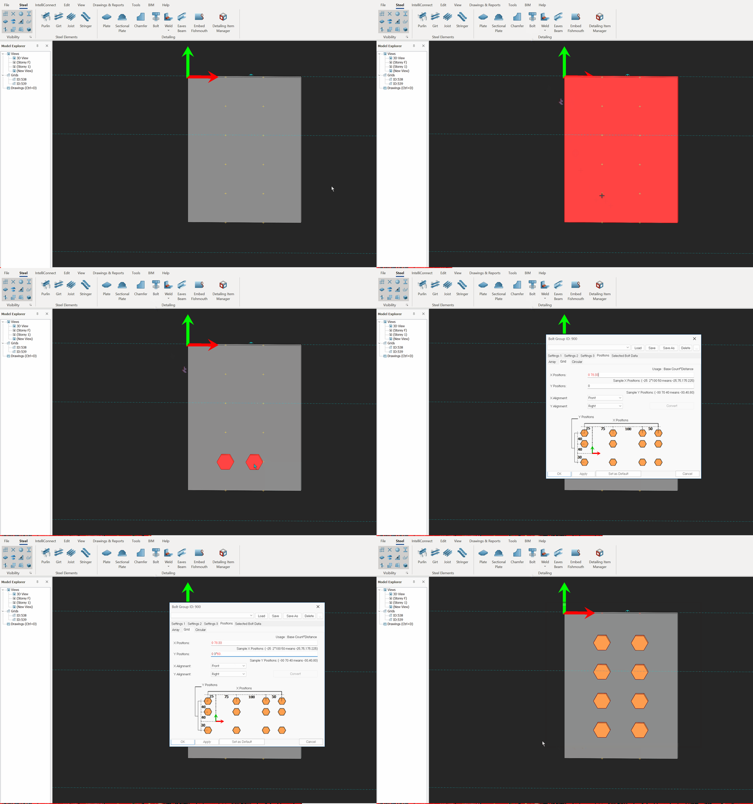
The Z-direction of the bolt group is the local Z-axis.
Weld
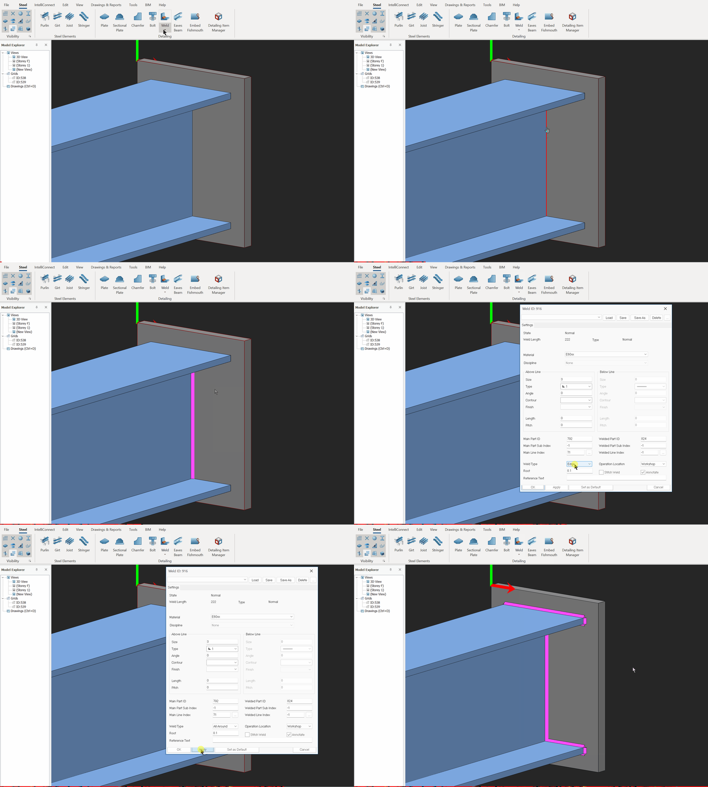
- Click on the icon, select the edge of the part to be welded.
- Then select the main part.
Weld Colors
- Pink: The weld is annotated and there is no problem with it.
- Green: The weld is annotated and there is a problem with it (i.e. no common edge).
- Yellow: The weld is not annotated and there is no problem with it.
- Blue: The weld is not annotated and there is a problem with it (i.e. no common edge)
For fixed weld, please refer to Modelling Welds for Piep Sections
Eaves Beam
- "Shift + Left Click" on icon to select eave beam profile section and set the parameters, then click OK.
- Click on the icon, select two points and follow by the third point which to designate the X-direction.
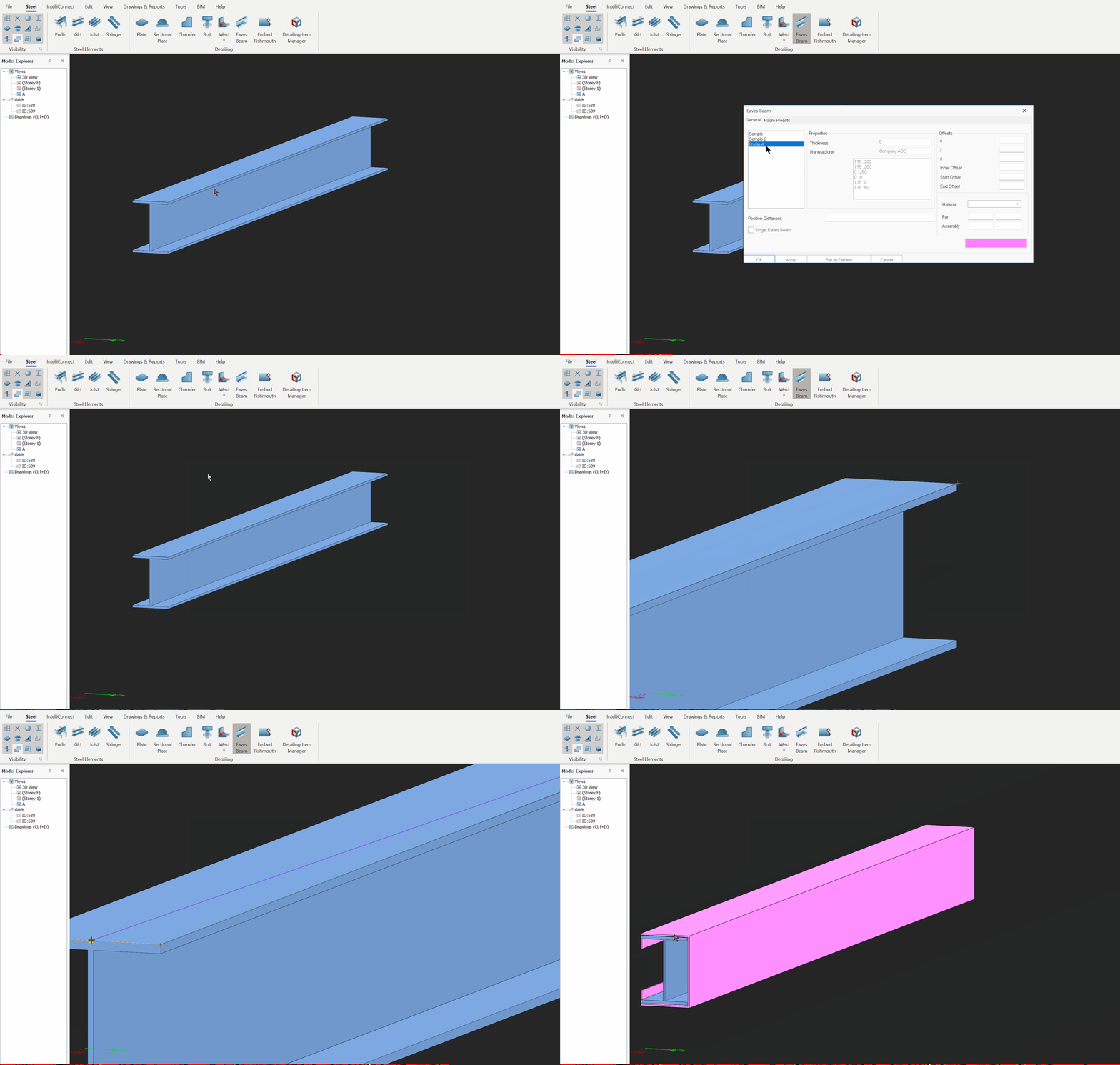
Eave Beam Profile Properties
To create own eave beam profile, open "FoldedPlateParameters.txt" file which located at "C:ProgramDataProtaProtaSteel 20XXPreferences".
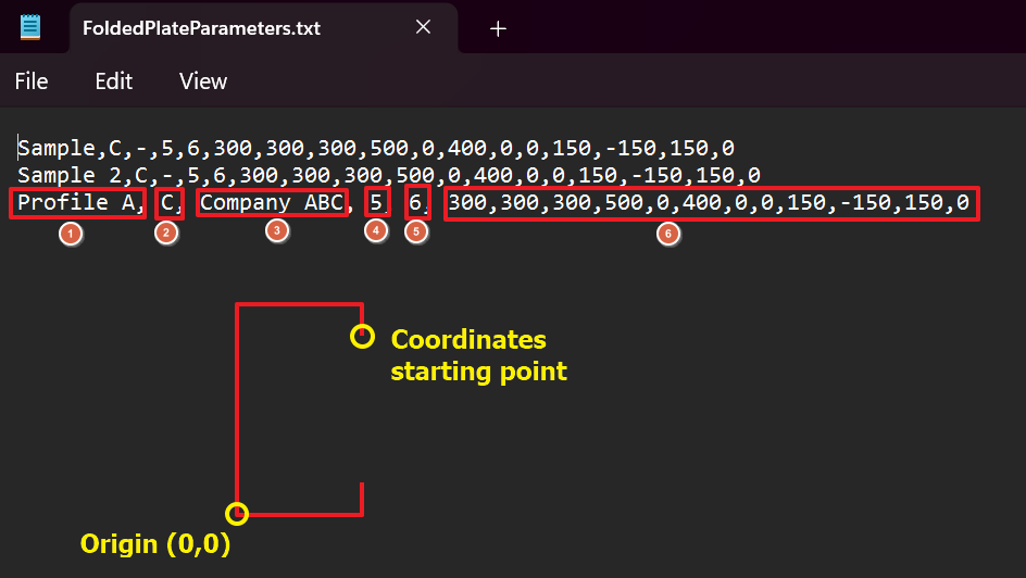
- Profile Name
- Profile shape
- Manufacturer Name
- Profile thickness
- Number of coordinates
- Coordinates of points
ProgramData is hidden folder which requires to turn on windows hidden folder feature.
Embed Fishmouth
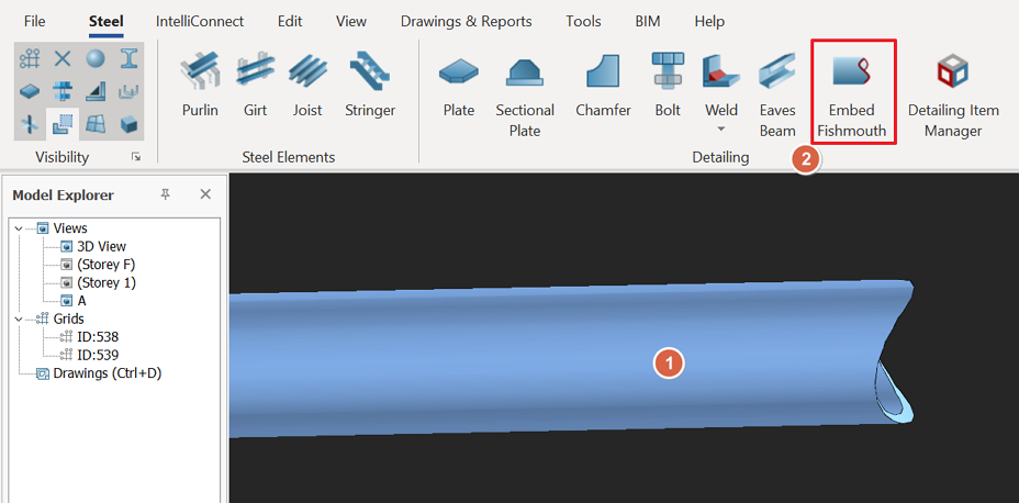
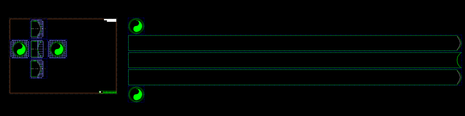
Embed Fishmouth is not a detailing modelling command. It is used for embedding cutting information of fishmouth of the profile (i.e. cutting pipe) in order it can be drawn on the part drawing with 1:1 scale.
- Select the cut pipe member and click on "Embed Fishmouth" icon to embed fishmouth information.
- In Part Drawing Setting, check option "Create Copy of Fishmouth Drawing in 1:1 Scale".
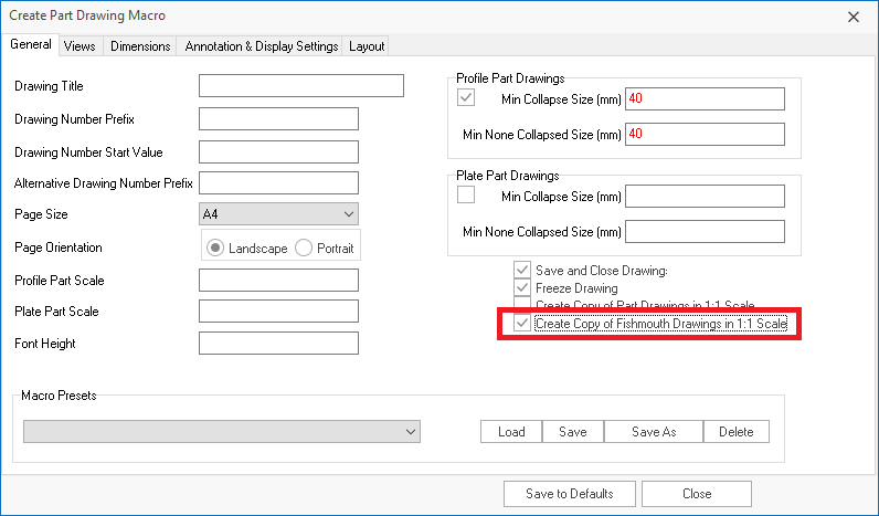
- When generate the part drawing, there is 1:1 scale drawing of the part located outside the drawing paper are with "unfolded" view of the pipe. This then can be print on paper on 1:1 scale and cut from the paper and wrapped around the pipe to facilitate the cut.
For Detailing Item Manager, please refer to Detail Item Manager