Creating Transfer Slab Model
A transfer slab is defined as a slab that is directly supporting discontinuous columns and walls directly, without beams.
The steps of modelling a transfer plate is similar to that of modelling a flat slab system:
- Model the supporting column and walls in transfer storey
- Model the transfer slabs in the transfer storey
- Model the discontinuous walls or columns in the storey above
- Transfer Member option MUST be checked for discontinuous walls or column.

The order in which you set up the elements of the model is not important, i.e. you can model the transfer slab first or the discontinuous columns and walls.
Modelling transfer slab is similar to flat slab, refer to : Working with Flat Slabs
The below is a example of a transfer plate model. Storey 1 is the transfer level. Storey 2 is where the discontinuous walls and columns are modeled.
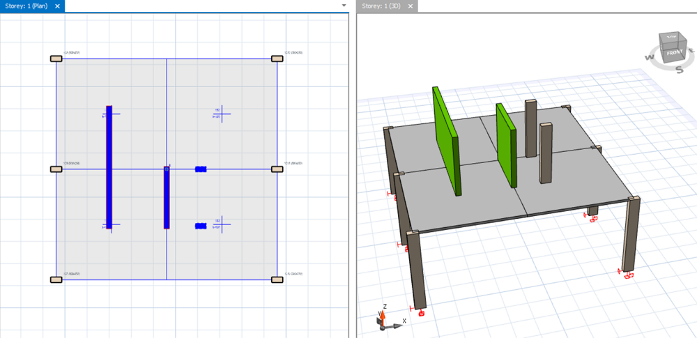

During modelling on the transfer slab in the transfer storey, it’s useful to switch on " Display Transfer Columns and Walls on Plan" via Visual Interrogation to show the discontinuous columns and walls just above the transfer storey. As shown above, the discontinuous walls and columns are shown in a different color (blue) on the plan view of ST01.
For more guidance refer to : How to show transfer or discontinuous columns and Walls on Plan view
Building Analysis
The analysis of the transfer plate can be included together with the building analysis :
- In the default analysis, the slabs are excluded from the analysis and only frame elements are considered (i.e. beams + columns + walls).
- The slab loads are calculated and decomposed to the beams before the analysis.
- Hence, if the model has a transfer slab supporting discontinuous columns and walls directly, the model will be unstable, since there are no frames (i.e. beams) to supports these discontinuous wall members.
Therefore, in situation where the model has transfer slabs, the slabs will need to be considered & included in the building analysis by meshing that particular floor slab:
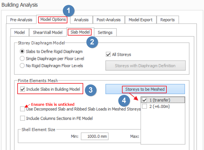
- Go Building Analysis menu > Slab Model > Check “Include Slabs in Building Model” (example as shown below).
-
Check the storey to be meshed
- For explanation of other parameters, please read this article : Model Options (Building Analysis)
-
When performing a transfer plate analysis, the walls that are discontinuous, immediately above the transfer plate needs to be analyzed as a FE shell model :
- This is to ensure that the wall element nodes are connected to the finite element nodes of the plate.
- To set the walls above the transfer plate to FE shell model, right click anywhere on the model plan > click on Member Tables > Wall Table > change the Analysis Model for the walls to FE Shell Model. (Example as shown below)

- If your PC meets the Recommended Hardware Specification, we recommend you also use FE Shell assumption for the transfer walls at all storeys above, so that assumption is consistent.
- However, if the analysis fails to run due to too many shells, other walls in floors above may be analyzed as Mid-Pier walls, i.e. set Analysis Model to "Default"
- In the same wall table, ensure "Transfer Member" is checked for the transfer wall at the transfer level only. This will suppress the warning of unsupported wall during Building Analysis.
- In Building Analysis menu > Model Options > ShearWall Model > Under "Wall Model" choose " Mid-pier Model" :
- This means that only walls which are specifically assigned to use "FE Shell Model" in the wall properties will use "FE Shell Model"
- All other walls which has been assigned "Default", e.g. non-transfer walls will use "Mid-pier Model"
- This will ensure the analysis model size is kept optimum so that analysis can run faster and to completion.

FE Floor Analysis should not be used for transfer plate models. The reason is the lateral analysis cannot be accurately captured by FE Floor Analysis.
Verify results in Analytical Model
After Building Analysis, go to Analytical Model to check and verify the results. For example you should verify :
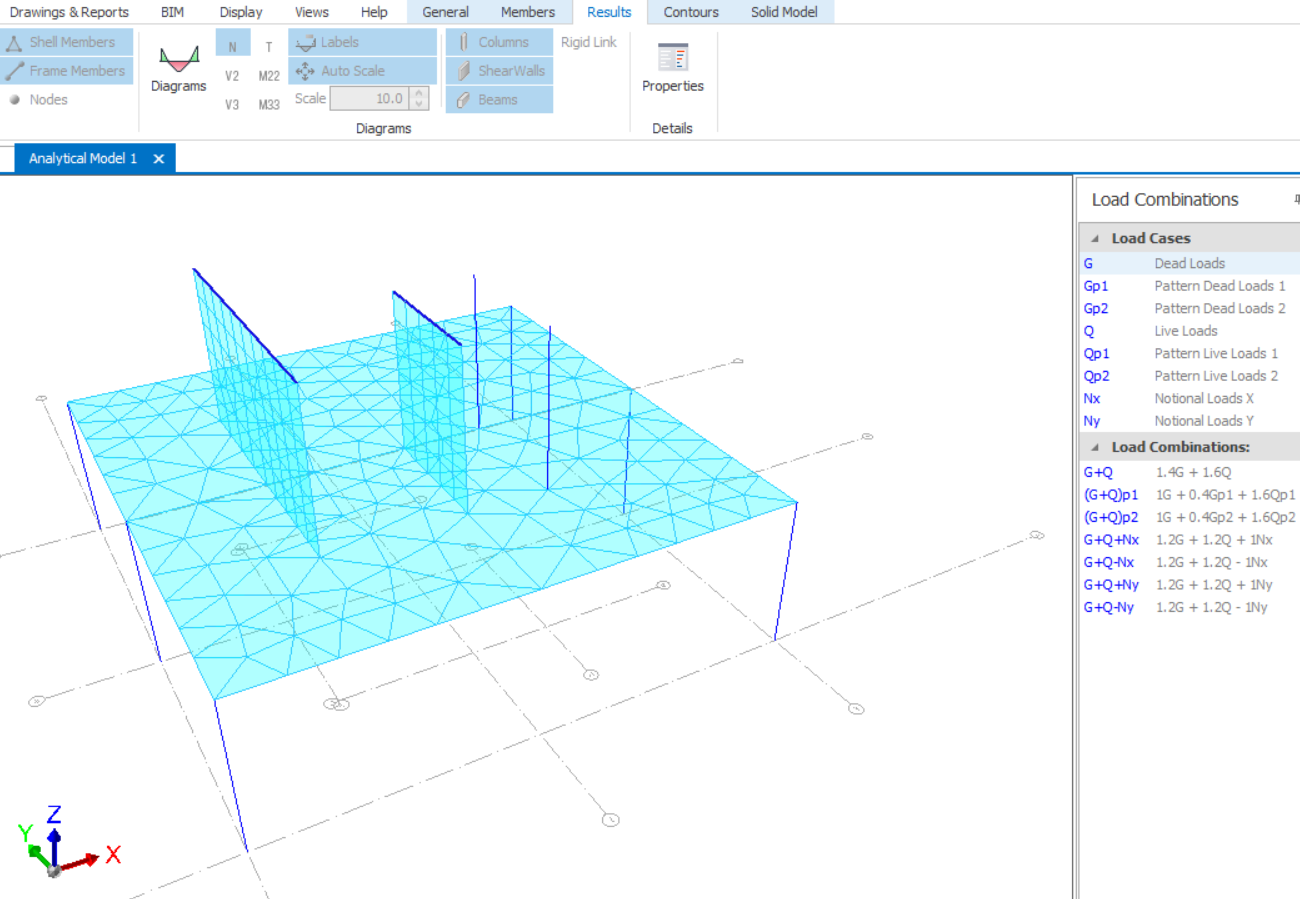
- Whether the discontinuous walls and columns are properly supported by the slabs by checking the connectivity of the shell and frame elements (as shown below)
- Whether all the elements deflect as connected entities by observing the "Displacements" of the analytical model. Select "Animation" to better visualize the displacements (as shown below)
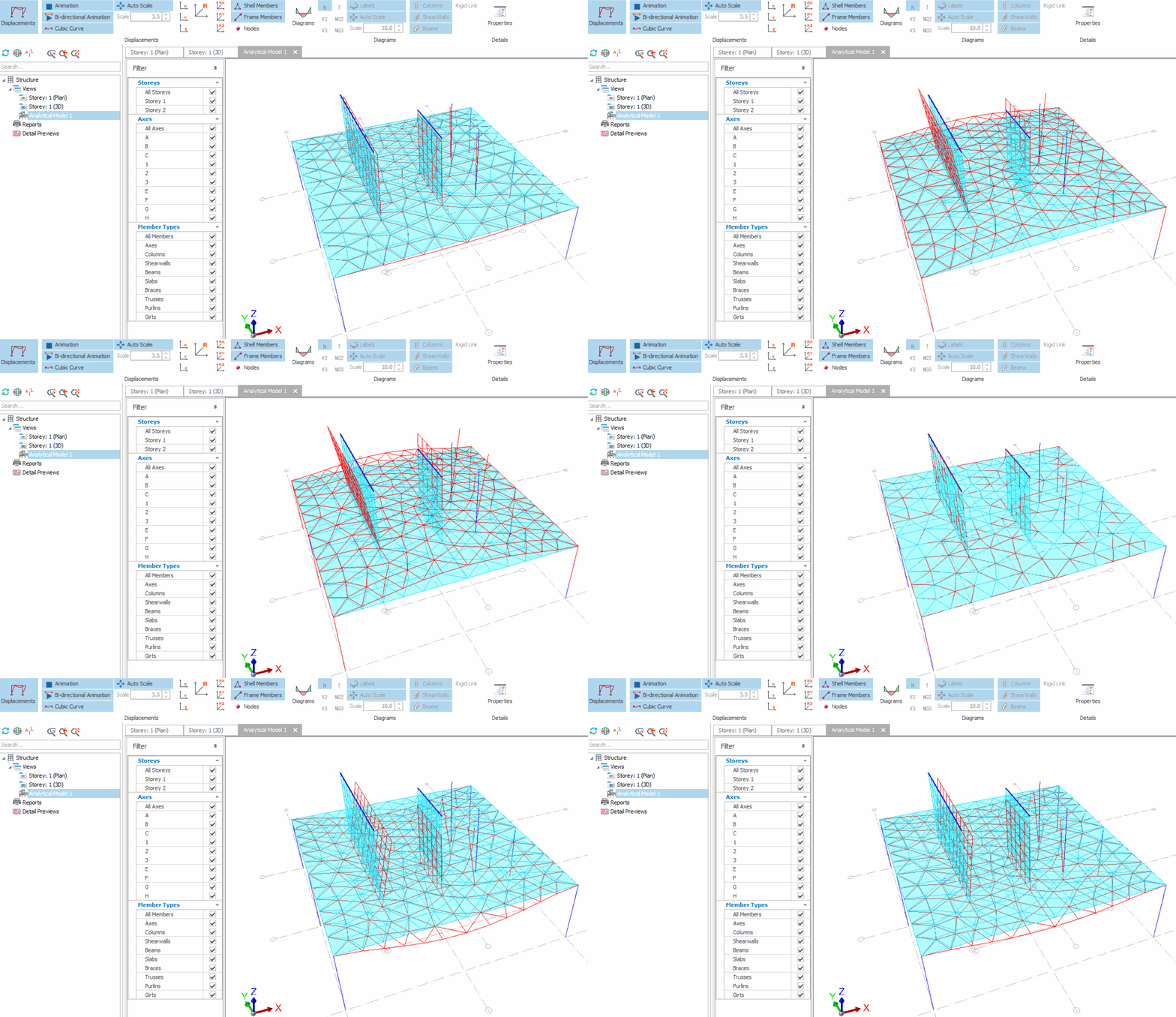

If you get any warning messages, you can identify the causes by referring to this article : How to check singularity or large deformation warnings during Building Analysis
Design of Transfer Slab
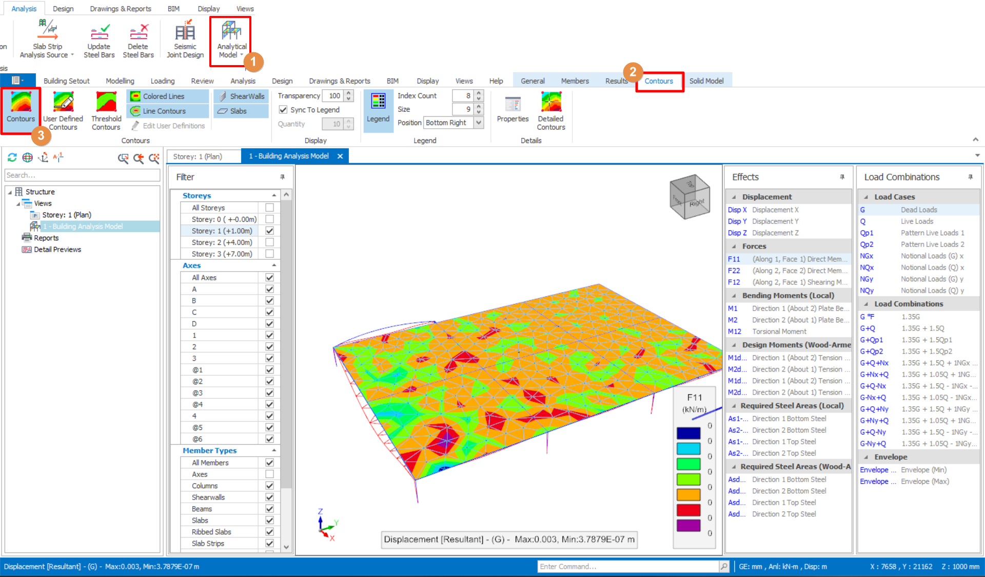
For the design of transfer slab, you will need to look at the design contours by going to the Building Analytical Model > Contours tab > Then select Contours icon.
- This allows you to inspect the contours for Area of required steel, similar to how you will design a flat slab model.
- The steps on how to deduce the final reinforcement is outlined in the Flat Slab Reinforcement Design